
")
The home handyman periodically needs to measure the circuit parameters. Check what voltage is currently in the network, whether the cable is not frayed, etc. For these purposes there are small devices – multimeters. With small size and cost, they allow you to measure various electrical parameters. On how to use a multimeter and we will talk further.
Зміст статті
External structure and functions
Recently, specialists and radio amateurs mainly use electronic models of multimeters. This does not mean that arrow ones are not used at all. They are indispensable when due to strong interference electronic ones simply do not work. But in most cases we deal with digital models.
There are different modifications of these measuring devices with different measurement accuracy, different functionality. There are automatic multimeters, in which the switch has only a few positions – they choose the nature of the measurement (voltage, resistance, current) and the device chooses the limits of measurement itself. There are models that can be linked to a computer. They transmit measurement data directly to the computer, where they can be saved.
But most home masters use inexpensive models of medium accuracy class (with a digit capacity of 3.5, which provides an accuracy of readings of 1%). These are common multimeters dt 830, 831, 832, 833. 834, etc. The last digit shows the “freshness” of the modification. Later models have a wider functionality, but for home use these new features are not critical. Working with all these models is not much different, so we will talk in general about the techniques and the order of actions.
Structure of the electronic multimeter
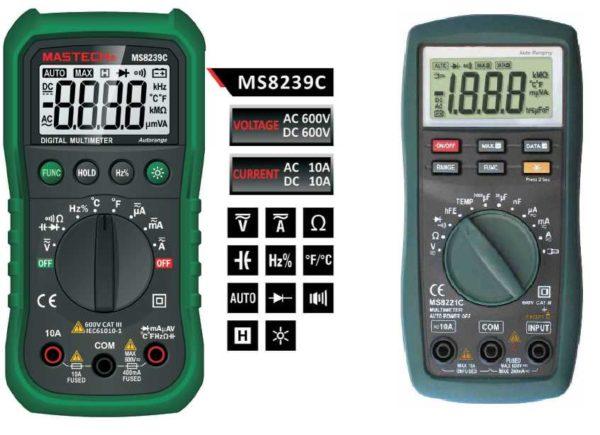
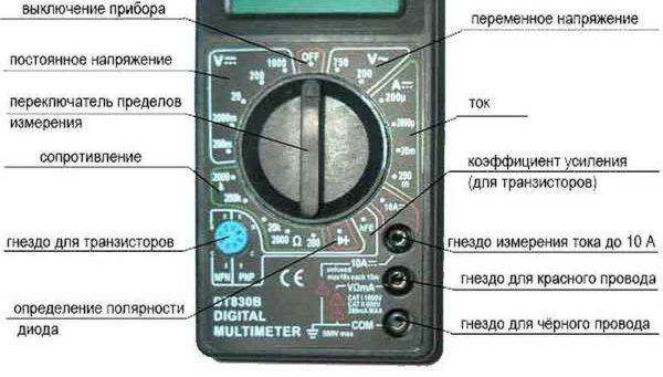
Before using a multimeter, let’s study its structure. Electronic models have a small LCD screen on which the results of measurements are displayed. Below the screen there is a range switch. It rotates around its axis. With the part marked with a red dot or arrow, it indicates the current type and range of measurement. Around the switch there are marks, by which the type of measurement and its range are set.
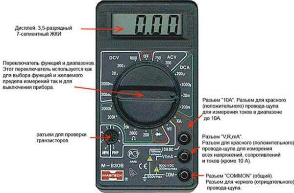
Below on the body there are sockets for connecting probes. Depending on the model, there are two or three sockets, and there are always two probes. One positive (red color), the second negative – black. The black stylus is always connected to the socket labeled “COM” or COMMON or labeled “ground”. The red one goes into one of the free sockets. If there are always two sockets, there is no problem, if there are three sockets, it is necessary to read in the manual, when measuring in which socket to insert the “plus” probe. In most cases, the red probe is plugged into the middle socket. This is how most of the measurements are performed. The upper socket is necessary if you are going to measure current up to 10 A (if more, then also in the middle socket).
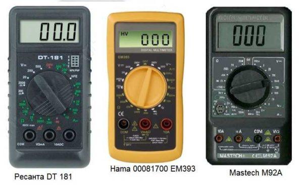
There are models of testers in which the sockets are located not on the right, but at the bottom (for example, multimeter Resanta DT 181 or Hama 00081700 EM393 on the photo). There is no difference in connection in this case: black to the socket labeled “COM”, and red according to the situation – when measuring currents up to 200 mA to 10 A – in the rightmost socket, in all other situations – in the middle one.
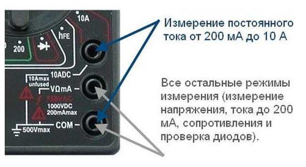
There are models with four sockets. In this case, there are two sockets for measuring current – one for microcurrents (less than 200 mA), the second for current from 200 mA to 10 A. Once you understand what is available in the device, you can start to understand how to use the multimeter.
Switch position
The mode of measurement depends on the position of the switch. At one of its ends there is a dot, it is usually colored white or red. This is the end that indicates the current mode of operation. In some models, the switch is made in the form of a truncated cone or has one edge pointed. This sharp edge is also a pointer. To make it easier to work, you can put a bright color on this pointing edge. This can be nail polish or some kind of abrasion-resistant paint.
By turning this switch you change the operating mode of the instrument. If it stands vertically up, the instrument is off. In addition, there are the following positions:
- V with a wavy line or ACV (to the right of the “off” position)- AC voltage measurement mode;
- A with a straight line – DC current measurement;
- A with a wavy line – AC current measurement (this mode is not available on all multimeters, on the above photos it is not present);
- V with a straight line or the inscription DCV (to the left of the off position) – to measure DC voltage;
- Ω – to measure resistances.
There are also positions for determining transistor gain and determining diode polarity. There may be others, but their purpose should be found in the manual for a particular instrument.
Measurements
Using an electronic tester is convenient because you do not need to look for the right scale, count the divisions, determining the readings. They will appear on the screen with an accuracy of two decimal places. If the measured value has polarity, the minus sign will be displayed. If there is no minus, the measurement value is positive.
How to measure resistance with a multimeter
To measure resistance, move the switch to the zone marked with the letter Ω. Choose any of the ranges. One probe is applied to one input, the second – to the other. The numbers that will appear on the display are the resistance of the element you are measuring.
Sometimes the screen displays not numbers. If “popped up” 0, it means that you need to change the range of measurement to a smaller one. If the words “ol” or “over” pop up, it is “1”, the range is too small and it should be increased. Here are all the tricks of measuring resistance with a multimeter.
How to measure the current
To choose the measurement mode, you must first determine whether the current is direct or alternating. There may be problems with measuring the parameters of alternating current – this mode is not available on all models. But the procedure regardless of the type of current is the same – only the position of the switch changes.
Direct current
So, having determined the type of current, we set the switch. Next, it is necessary to decide in which socket to connect the red probe. If you do not know even approximately what values to expect, so as not to accidentally burn the device, it is better to first install the probe in the upper (leftmost in other models) socket, which is signed “10 A”. If the readings will be small – less than 200 mA, move the probe to the middle position.
The same is the case with the selection of the measuring range: first you set the maximum range, if it turns out to be too large, switch to the next smaller one. So until you see the readings.
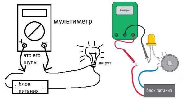
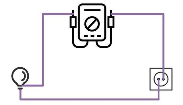
To measure the current, the device must be included in the circuit break. The connection diagram is given in the figure. In this case, it is important to set the red probe on the “+” of the power source and black touch the next element of the circuit. Do not forget when measuring that the power supply is present, work carefully. Do not touch the uninsulated ends of the stylus or circuit elements with your hands.
AC current
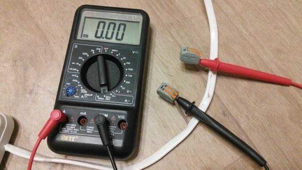
You can try the AC measurement mode on any load connected to the household power supply and thus determine the current consumption. Since in this mode, too, the instrument must be included in the circuit break, this can be difficult. It is possible, as in the photo below, to make a special cord for measurements. At one end of the cord is a plug, at the other – a socket, one of the wires to cut, on the ends of the attach two WAGO connectors. These are good because they also allow you to clamp the feeler gauges. After the measuring circuit is assembled, let’s start measuring.
Turn the switch to the “AC” position, select the measurement limit. Keep in mind that exceeding the limits can disable the device. At best, the fuse will burn out, at worst, the “stuffing” will be damaged. Therefore, we act according to the scheme suggested above: first set the maximum limit, then gradually reduce it. (don’t forget to rearrange the probes in the sockets).
Now everything is ready. First we connect the load to the socket. We can use a table lamp. Plug the plug into the mains. The numbers appear on the screen. This is the current consumed by the lamp. In the same way you can measure the current consumption of any device.
Measuring voltage
Voltage also comes in alternating or constant, accordingly, choose the desired position. The approach to selecting the range is the same: if you don’t know what to expect, set it to the maximum and gradually switch to a smaller scale. Don’t forget to check whether the probes are connected correctly and in the right sockets.
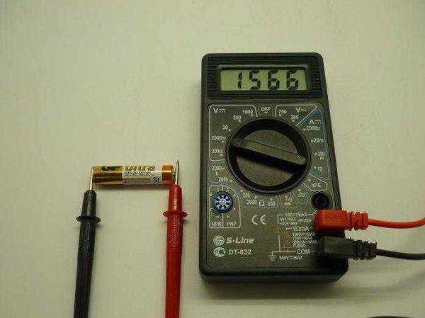
In this case, the meter is connected in parallel. For example, you can measure the voltage of an accumulator or an ordinary battery. Set the switch to DC voltage measurement mode, since we know the expected value, select a suitable scale. Then touch the battery on both sides with the stylus. The figures on the screen will be the voltage that this battery produces.
How to use a multimeter to measure alternating voltage? Yes exactly the same way. Just choose the right measurement limit.
Test the wires with a multimeter
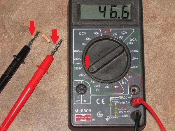
This operation allows you to check the integrity of wires. On the scale, we find the sign of the piercing – a schematic image of the sound (look at the photo, but there the mode is double, and there can only be a sign of the piercing). This image is chosen because if the wire is whole, the device makes a sound.
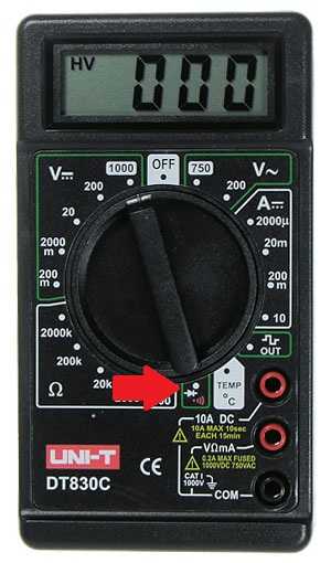
We put the switch in the desired position, probes are connected as usual – in the lower and middle socket. We touch one probe to one edge of the conductor, the other – to the other. If we hear a sound, the wire is intact. In general, as you can see, it is not difficult to use a multimeter. Everything is easy to memorize.


Using a multimeter is super handy! I remember fixing my old stereo—just popped out the tester, checked the voltage, and boom, problem solved! Everyone should have one. It makes troubleshooting so much easier and saves you a ton of cash! Trust me, it’s a game changer!
I remember the first time I used a multimeter. I was checking the battery in my bike. Just plugged in the leads, set it to volts, and bam! The reading saved me a lot of hassle. It’s super handy for quick checks around the house!
I remember the first time I used a multimeter to check my car battery. It was a game-changer! Just set it to the right voltage, connect the probes, and boom – you get instant readings. Super helpful for anyone diving into DIY repairs. Worth mastering for sure!