

Anyone who has ever dealt with wires and electricity has noticed that conductors always have different colors of insulation. This is done for a reason. The colors of wires in electricity are designed to make it easier to recognize the phase, neutral and ground wires. All of them have a certain coloring and are easily distinguished when working. About what is the color of wires phase, zero, ground and will be discussed further.
Vsebina članka
How the phase wires are colored
When working with wiring, the phase wires pose the greatest danger. Touching the phase, under certain circumstances, can be lethal, because, probably, for them chosen bright colors. In general, the colors of wires in electricity allow you to quickly determine which of the bundle of wires are the most dangerous and work with them very carefully.

Most often phase conductors are red or black, but there are other colors: brown, lilac, orange, pink, purple, white, gray. These are all the colors that phases can be painted in. They will be easier to deal with if you exclude the neutral wire and the ground.
On the schemes, phase wires are denoted by the Latin (English) letter L. If there are several phases, a numerical designation is added to the letter: L1, L2, L3 for a three-phase network of 380 V. In another version, the first phase is designated by the letter A, the second – B, the third – C.
The color of the grounding conductor
According to modern standards, the grounding conductor has a yellow-green color. It usually looks like yellow insulation with one or two longitudinal bright green stripes. But there are also coloring of transverse yellow-green stripes.
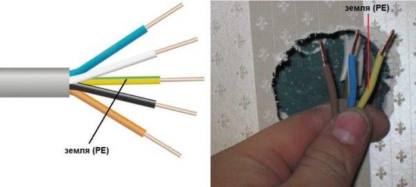
In some cases, the cable may have only yellow or bright green conductors. In such a case, the “ground” is exactly this color. The same colors it is shown on the schematics – more often bright green, but can be yellow. The “ground” is signed on the schematics or on the equipment with the Latin (English) letters PE. The same labeled and the contacts to which the “ground” wire should be connected.
Sometimes professionals call the ground wire “zero protective”, but do not be confused. It is exactly the earth wire, and it is protective because it reduces the risk of electric shock.
What color is the neutral wire
Zero or neutral has a blue or blue color, sometimes – blue with a white stripe. Other colors in electricity for the designation of zero are not used. So it will be in any cable: three-core, five-core or with a large number of conductors.
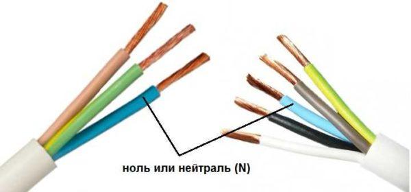
Blue color is usually drawn “zero” on schemes, and signed with the Latin letter N. Specialists call it a working zero, since it, unlike grounding, participates in the formation of the power supply circuit. When reading the scheme, it is often defined as “minus”, while the phase is considered “plus”.
How to check the correctness of labeling and disconnection
Colors of wires in electricity are designed to speed up the identification of conductors, but relying only on colors is dangerous – they could be connected incorrectly. Therefore, before starting work, it is worth making sure that you have correctly identified their belonging.
Take a multimeter and/or an indicator screwdriver. It is easy to work with a screwdriver: when you touch the phase, the LED mounted in the housing lights up. So it will be easy to identify the phase conductors. If the cable is two-core, there is no problem – the second conductor is zero. But if the wire is three-core, you will need a multimeter or tester – with their help we will determine which of the remaining two is phase, which is zero.
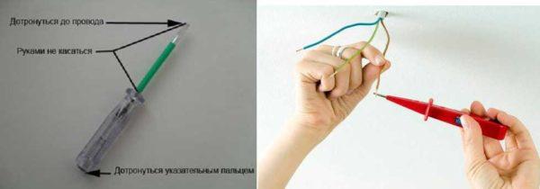
On the device, we set the switch so that the selected was jackal more than 220 V. Then we take two feelers, hold them by their plastic handles, carefully touch the metal rod of one feeler to the found phase wire, the second – to the supposed zero. The screen should show 220 V or the current voltage. In fact, it may be much lower – this is our reality.
If 220 V or a little more is displayed, it is zero, and the other wire is presumably ground. If the value is less, continue checking. One probe again touch the phase, the second – to the presumed ground. If the readings of the device are lower than the first measurement, before you “ground” and it should be green in color. If the readings are higher, it means that somewhere messed up and in front of you “zero”. In such a situation there are two options: look for where exactly the wrong wires were connected (preferable) or just move on, having memorized or marked the existing position.
So, remember that the multimeter readings are always higher when probing the “phase-zero” pair than when probing the “phase-ground” pair.
And, in conclusion, let me advise you: when laying wiring and connecting wires, always connect the conductors of the same color, do not confuse them. This can lead to disastrous results – at best, equipment failure, but there may be injuries and fires.

")


