

When organizing a water supply system at home, you need not only a pump, but also automation to ensure its operation. One of the necessary devices is a water pressure switch. This small device switches the pump on when the system pressure drops and switches it off when the threshold value is reached. The value of the on and off parameters can be adjusted. About how this device is arranged, how to connect it and how to regulate – in the article.
Inhoud van het artikel
Purpose and device
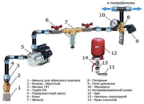
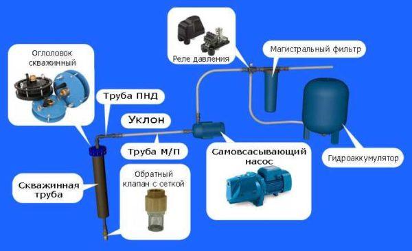
To maintain a constant pressure in the water supply system of a private house, two devices are needed – a hydroaccumulator and a pressure switch. Both of these devices through the pipeline are connected to the pump – the pressure switch is located in the middle between the pump and the hydroaccumulator. Most often it is located in the immediate vicinity of this tank, but some models can be installed on the pump body (even submersible). Let’s understand the purpose of these devices and how the system works.
Hydroaccumulator – a container divided by an elastic pear or diaphragm into two halves. In one is under some pressure air, in the second is pumped water. The water pressure in the accumulator and the amount of water that can be pumped into it is regulated by the amount of air pumped in. The more air there is, the higher the pressure is maintained in the system. At the same time, however, less water can be pumped into the tank. Usually no more than half of the volume can be pumped into the tank. That is, in the hydroaccumulator volume of 100 liters will be able to pump no more than 40-50 liters.
For normal operation of household appliances requires a range of 1.4 atm – 2.8 atm. In order to maintain this range, a pressure switch is required. It has two limits of operation – upper and lower. When the lower limit is reached, the relay starts the pump, it pumps water into the accumulator, and the pressure in the accumulator (and in the system) increases. When the pressure in the system reaches the upper limit, the relay switches off the pump.
In the accumulator circuit, water is drawn from the tank for some time. When enough water has drained out for the pressure to drop to the lower threshold, the pump is switched on. This is how the system works.
The device of the pressure switch
This device consists of two parts – electrical and hydraulic. The electrical part is a group of contacts that closes and opens to turn on/off the pump. The hydraulic part is a diaphragm that exerts pressure on a metal base and springs (large and small) by means of which the on/off pressure of the pump can be changed.
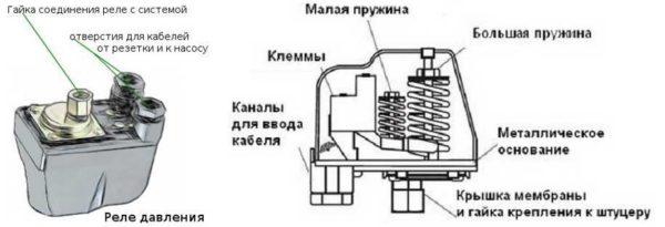
The outlet of the hydraulic part is located at the back of the relay. It can be an outlet with male thread or with an American-style nut. The second option is more convenient when installing – in the first case, it is necessary either to look for an adapter with a cap nut of suitable size or to twist the device itself, screwing it onto the thread, and this is not always possible.
The inputs of the electrical part are also on the back of the case, and the terminal block itself, where the wires are connected, is hidden under the cover.
Soorten en variëteiten
Water pressure switches are of two types: mechanical and electronic. Mechanical ones are much cheaper and are usually preferred, and electronic ones are mostly brought to order.
| Naam | Pressure control limit | Factory settings | Manufacturer/country | Protection class | Prijs |
|---|---|---|---|---|---|
| RDM-5 Gileks | 1- 4,6 atm | 1.4 – 2.8 atm | Jileks/Russia | IP 44 | 13-15$ |
| Italtecnica PM/5G (m) 1/4″ | 1 – 5 atm | 1,4 – 2,8 atm | Italië | IP 44 | 27-30$ |
| Italtecnica PT/12 (m) | 1 – 12 atm | 5 – 7 atm | Italië | IP 44 | 27-30$ |
| Grundfos (Condor) MDR 5-5 | 1,5 – 5 atm | 2,8 – 4,1 atm | Duitsland | IP 54 | 55-75$ |
| Italtecnica PM53W 1″ | 1.5 – 5 atm | Italië | 7-11 $ | ||
| Genebre 3781 1/4″ | 1 – 4 atm | 0,4 – 2,8 atm | Spain | 7-13$ |
The difference in prices in different stores can be more than significant. Although, as usual, buying cheap copies, there is a risk of running into a fake.
Connecting the water pressure switch
Water pressure switch for the pump is connected to two systems at once: to electricity and water supply. It is installed permanently, as there is no need to move the device.
Electrical part
To connect the pressure switch, a dedicated line is not necessary, but it is desirable – more chances that the device will work longer. A cable with a solid copper conductor with a cross-section of at least 2.5 sq. mm should run from the switchboard. It is desirable to install a bundle of automatic circuit breaker + RCD or difavtomat. Parameters are selected by current and depend more on the characteristics of the pump, as the water pressure switch consumes very little current. In the scheme is mandatory grounding – the combination of water and electricity create a zone of increased danger.
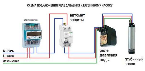
Cables are inserted into special glands on the rear side of the housing. Under the cover there is a terminal block. It has three pairs of contacts:
- ground – the corresponding conductors from the switchboard and the pump are connected;
- line or “line” terminals – for connecting the phase and neutral wires from the switchboard;
- terminals for the same wires from the pump (usually on the block above).
Connection is standard – conductors are stripped of insulation, inserted into the connector, tightened with a clamping bolt. Pulling the conductor, check whether it is securely clamped. After 30-60 minutes the bolts can be tightened, as copper is a soft material and the contact may loosen.
Connection to the pipeline
There are different ways to connect the water pressure switch to the plumbing system. The most convenient option is to install a special adapter with all the required outputs – a five-water fitting. The same system can be assembled from other fittings, just the finished version is always used denser.
It is screwed onto the spigot on the back of the body, to the other outputs connect the hydroaccumulator, the supply hose from the pump and the main line that goes to the house. A strainer and pressure gauge can also be installed.
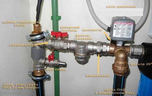
Manometer – a necessary thing – to control the pressure in the system, monitor the settings of the relay. Mud filter is also a necessary device, but it can be installed separately on the pipeline from the pump. In general, a whole system of filters for water purification is desirable there.
In such a scheme, at high flow rates, water is fed directly into the system – bypassing the hydroaccumulator. It starts to fill up after all taps are closed in the house.
Adjusting the water pressure switch
Let’s consider the adjustment process of the most popular copy – RDM-5. It is produced by different factories. The limits of adjustment vary, since different sized water pipes require different pressures. From the factory, this device comes out with a basic setting. Usually it is 1,4-1,5 atm – the lower threshold and 2,8-2,9 atm – the upper threshold. If you are not satisfied with any parameter, you can reconfigure it as required. This procedure is usually necessary when installing a Jacuzzi: the standard pressure of 2.5-2.9 atm is not sufficient for the desired effect. In most other cases, no readjustment is necessary.
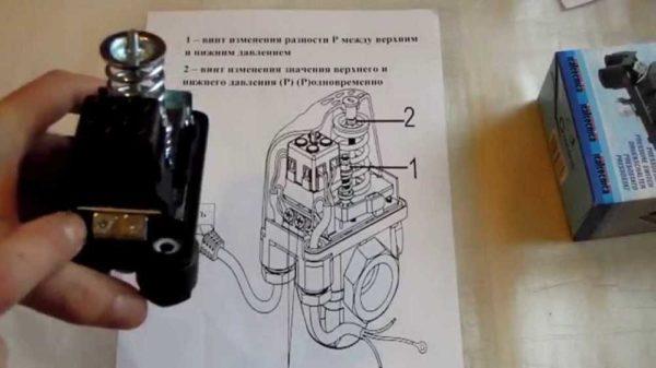
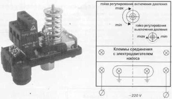
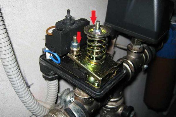
The water pressure switch РДМ-5 has two springs, which regulate the threshold of switching off/on the pump. These springs differ in size and purpose:
- the large one regulates the limits (upper and lower at once);
- the smaller one changes the delta – the gap between the upper and lower limit.
The parameters are changed by tightening or loosening the nuts on the springs. If the nuts are tightened, the pressure increases, if loosened, the pressure decreases. It is not necessary to twist the nuts too much, one turn is a change of about 0.6-0.8 atm, which is usually a lot.
How to determine relay thresholds
The threshold for switching on the pump (and the lower pressure threshold on the water pressure switch) are related to the pressure in the air part of the hydroaccumulator – the minimum pressure in the system should be 0,1-0,2 atm higher. For example, if the pressure in the tank is 1.4 atm, the cut-off threshold is desirable 1.6 atm. With these parameters, the tank diaphragm will last longer. But to ensure that the pump also works in normal conditions, look at its characteristics. It also has a lower pressure threshold. So, it should not be higher than the selected value (below or equal). Based on these three parameters and select the threshold of switching on.
By the way, you should check the pressure in the accumulator before setting – there are significant deviations from the stated parameters. Under the removable cover (in different models looks and is located in different places) hidden nipple. Through it you can connect a pressure gauge (you can connect a car or the one you have) and see the actual pressure. By the way, it can be corrected through the same nipple – to increase or decrease it if necessary.
The upper threshold – pump shut-off – is automatically set during adjustment. The relay is set to some pressure difference (delta) in the initial state. This difference is usually 1.4-1.6 atm. So if you have set the switch on, for example, at 1.6 atm, the switch off threshold of 3.0-3.2 atm will be automatically set (depends on the relay settings). If you need a higher pressure (to raise the water to the second floor, for example, or the system has many water points), you can increase the cut-off threshold. But there are limitations:
- The parameters of the relay itself. The upper limit is fixed and in household models usually does not exceed 4 atm. It is simply not possible to set more.
- The upper limit of the pump pressure. This parameter is also fixed and the pump should be switched off not less than 0,2-0,4 atm before the declared characteristic. For example, the upper threshold of the pump pressure is 3.8 atm, the cut-off threshold on the water pressure switch should be no higher than 3.6 atm. But for the pump to work long and without overloads, it is better to make the difference more – overloads are too bad for the working life.
That is all on the choice of settings of the water pressure switch. In practice, when setting up the system have to adjust the selected parameters to one side or the other, because you need to pick up everything so that all points of water intake, including household appliances. Therefore, it is often said that the parameters are chosen by “scientific poke”.
Setting the water pressure switch for a pump or pumping station
To set up the system, you will need a reliable pressure gauge, the readings of which can be trusted. It is connected to the system near the pressure switch.
The adjustment process consists of twisting two springs: a large spring and a small spring. If you need to raise or lower the lower threshold (pump on), turn the nut on the large spring. Turning it clockwise raises the pressure, turning it counterclockwise lowers it. Turn it a very small amount – half a turn or so.
The sequence of actions is as follows:
- Start the system, on the pressure gauge monitor at what pressure the pump turned on and off.
- Press or release the large spring.
- Turn on and check the parameters (at what pressure the pump is switched on, at what pressure it is switched off). Both values are shifted to the same value.
- If necessary, adjustments are made (adjust the large spring again).
- Once the lower threshold is set as you want it to be, adjust the pump cut-off threshold. To do this, the small spring is tightened or lowered. Do not twist the nut on it too much – half a turn is usually enough.
- Turn the system on again and look at the results. If everything is satisfactory, stop here.
What else should I know about adjusting the water pressure switch? That not all models have the ability to change the delta, so look more carefully when buying. There are pressure switches for the pump in waterproof and dust-protected housing. They can be placed in a pit, some models can be installed directly on the pump housing, if it has such an outlet.
In some water pressure switches there is also an idle (dry run) relay, in general this device is in a separate housing, but there are also combined. Protection from idle running is necessary to prevent the pump from breaking if suddenly there is no water in the well or borehole. Some pumps have built-in protection of this type, for others separately buy and install a relay separately.


