

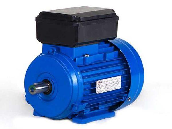
Most often our houses, plots, garages are connected to a single-phase 220 V network. Therefore, equipment and all self-made devices are made so that they work from this power source. In this article we will consider how to correctly make the connection of a single-phase motor.
Inhoud van het artikel
Asynchronous or collector: how to distinguish
In general, you can distinguish the type of motor by the plate – nameplate – on which its data and type are written. But this is only if it has not been repaired. After all, under the hood can be anything. So if you are not sure, it is better to determine the type yourself.
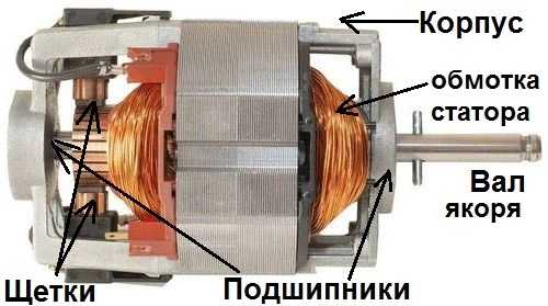
How collector motors are organized
Distinguish between induction and collector motors can be distinguished by the structure. Collector motors necessarily have brushes. They are located near the collector. Another mandatory attribute of this type of engine is the presence of a copper drum, divided into sections.
Such motors are produced only single-phase, they are often installed in household appliances, since they allow you to get a large number of revolutions at the start and after acceleration. They are also convenient because they easily allow you to change the direction of rotation – you only need to change the polarity. It is also easy to organize the change of rotation speed by changing the amplitude of the supply voltage or its cut-off angle. That is why such motors are used in most household and construction equipment.
The disadvantages of collector motors are high noisiness of work at high speeds. Think of a drill, a Bulgarian, a vacuum cleaner, a washing machine, etc.. Noise at their work costs decent. At low speeds, collector motors are not so noisy (washing machine), but not all tools work in this mode.
The second unpleasant moment – the presence of brushes and constant friction leads to the need for regular maintenance. If the current collector is not cleaned, contamination with graphite (from rubbing brushes) can lead to the fact that neighboring sections in the drum connect, the motor will simply stop working.
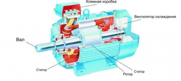
Asynchronous
The asynchronous motor has a stator and rotor, can be single and three-phase. In this article we consider the connection of single-phase motors, so we will talk only about them.
Induction motors are characterized by a low level of noise during operation, so they are installed in equipment, the noise of which is critical. These are air conditioners, split-systems, refrigerators.
There are two types of single-phase induction motors – bifilar (with a starting winding) and capacitor. The difference is that in bifilar single-phase motors, the starting winding works only until the motor accelerates. After it is switched off by a special device – centrifugal switch or starting relay (in refrigerators). This is necessary because after acceleration it only reduces the efficiency.
In capacitor single-phase motors, the capacitor winding runs all the time. The two windings, the main winding and the auxiliary winding, are offset relative to each other by 90°. This allows the direction of rotation to be reversed. The capacitor on such motors is usually attached to the housing and can be easily identified by this feature.
A more precise determination of whether you are looking at a bifilar or capacitor motor can be made by measuring the resistance of the windings. If the resistance of the auxiliary winding is twice as high (the difference can be even more significant), it is most likely a bifilar motor and this auxiliary winding is a starting winding, which means that a switch or starting relay must be present in the circuit. In capacitor motors, both windings are constantly in operation and connection of a single-phase motor is possible through an ordinary button, toggle switch, automatic machine.
Wiring diagrams for single-phase induction motors
With starting winding
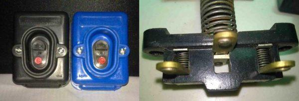
To connect a motor with a starting winding, you will need a button, which one of the contacts after switching on is opened. These open contacts must be connected to the starting winding. There is such a button in stores – it is a PNVS. Her middle contact is closed for the time of holding, and the two outer two contacts remain in the closed state.
First, by means of measurements we determine which winding is working and which winding is starting. Usually the lead from the motor has three or four wires.
Consider the variant with three wires. In this case, two windings are already combined, that is, one of the wires is common. Take a tester, measure the resistance between all three pairs. The working winding has the lowest resistance, the average value is the starting winding, and the highest value is the common output (the resistance of two windings in series is measured).
If there are four leads, they are called in pairs. Find two pairs. The one in which the resistance is less – working, in which the resistance is greater – starting. After that, connect one wire from the starting and working windings, lead out the common wire. In total there are three wires (as in the first variant):
- one from the working winding – working;
- from the starting winding;
- common.
With these three wires and work further – use them to connect a single-phase motor.
With all these 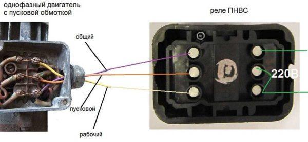
All three wires are connected to the button. It also has three contacts. Be sure to put the start wire on the middle contact (which is closed only during the start), the other two – on the extreme(arbitrarily). Connect the power cable (from 220 V) to the extreme input contacts of the power supply unit, connect the middle contact with a jumper to the working one(pay attention! not to the common one). Here is the whole scheme of switching on a single-phase motor with a starting winding (bifilar) through the button.
Condensator
When connecting a single-phase capacitor motor, there are options: there are three connection schemes and all with capacitors. Without them, the motor hums, but does not start (if you connect it according to the scheme described above).
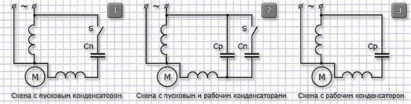
The first scheme – with a capacitor in the supply circuit of the starting winding – start well, but when operating, the power output is far from nominal, and much lower. The inclusion scheme with a capacitor in the connection circuit of the working winding gives the opposite effect: not very good performance at startup, but good performance. Accordingly, the first scheme is used in devices with heavy starting (concrete mixers, for example), and with a working condenser – if good performance is required.
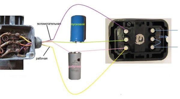
Scheme with two capacitors
There is a third option for connecting a single-phase motor (asynchronous) – to install both capacitors. It turns out something in between the above options. This scheme is realized most often. It is on the picture above in the middle or on the photo below in more detail. When organizing this scheme, you also need a button of PNVS type, which will connect the capacitor only during the start time, while the motor is “accelerating”. Then two windings will remain connected, and the auxiliary through the capacitor.
When realizing other schemes – with a single capacitor – you will need an ordinary button, automatism or toggle switch. There everything is connected simply.
Selection of capacitors
There is a fairly complex formula by which you can calculate the required capacitance accurately, but it is quite possible to get by with recommendations that are derived from many experiments:
- the working capacitor is taken at the rate of 70-80 µF per 1 kW of motor power;
- the starting capacitor – 2-3 times more.
The working voltage of these capacitors should be 1.5 times higher than the voltage of the network, that is, for a network of 220 volts take capacitors with a working voltage of 330 V and higher. And to make starting easier, look for a special capacitor for the starting circuit. They are labeled with the words Start or Starting, but you can take the usual ones.
Changing the direction of the motor
If after connecting the motor works, but the shaft does not rotate in the direction you want, you can change this direction. This is done by changing the windings of the auxiliary winding. When we assembled the circuit, one of the wires was fed to the button, the second one was connected to the wire from the working winding and brought out the common. This is where the conductors should be switched.

")


