

To understand what exactly is drawn on a schematic or drawing, you need to know the decoding of the icons used. This is called reading drawings. However, the standards have not been updated for a long time and some elements are drawn with errors. But, for the most part, the conventional designations of elements in electrical schemes are given in normative documents.
Artikkelens innhold
Regulatory base
Varieties of electrical circuits are about a dozen, the number of different elements that can be found there, numbering in the dozens, if not hundreds. To facilitate the recognition of these elements, introduced a unified conventional designations in electrical schemes. All the rules are prescribed in GOSTs. There are many of these regulations, but the basic information is in the following standards:
Studying GOSTs – a useful thing, but requires time, which is not everyone has a sufficient amount. Therefore, in this article we will give the conventional designations in electrical schemes – the main elemental basis for creating drawings and schemes of electrical wiring, schematic diagrams of devices.
Designation of electrical elements in schemes
Specialists, carefully looking at the scheme, can say what it is and how it works. Some can even immediately give out possible problems that may arise during operation. It’s simple – they have a good knowledge of circuitry and element base, and are also well oriented in the conventional designations of circuit elements. Such a skill is built up over the years, and for “dummies” it is important to memorize the most common for starters.
Electrical panels, cabinets, boxes
On the schemes of the electrical supply of a house or apartment, there will necessarily be a designation of an electrical panel or cabinet. In apartments, terminal devices are installed, since the wiring does not go further. In private houses can design the installation of a branching electrical cabinet, if from it will go the route to the electrical supply of other buildings that are at some distance from the house: bathhouse, summer kitchen, guest house. These designations are on the following picture.
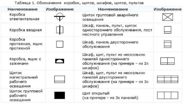
If we talk about the images of the stuffing of electrical panels, it is also standardized. There are conventional designations of RCDs, circuit breakers, buttons, current and voltage transformers and some other elements. They are shown in the following table.
Element base for wiring diagrams
When drawing or reading the scheme, the designations of wires, terminals, ground, zero, etc. will also be useful. This is simply necessary for a novice electrician or in order to understand what is depicted in the drawing and in what sequence its elements are connected.
An example of the use of the above graphic images is in the following diagram. Thanks to the letter designations everything and without graphics is clear, but duplication of information in the schemes has never been superfluous.
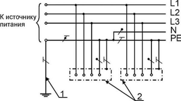
Image of sockets
On the wiring diagram should be marked the places of installation of outlets and switches. Types of outlets are many – for 220 V, 380 V, hidden and open type of installation, with a different number of seats, waterproof, etc. Give the designation of each, too long and to no purpose. It is important to remember how the main groups are depicted, and the number of contact groups is determined by the strokes.
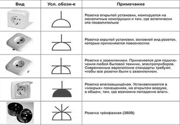
Outlets for single-phase 220 V network are designated on the schemes in the form of a semicircle with one or more protruding upward segments. The number of segments corresponds to the number of sockets on one body (the photo below is an illustration). When only one plug can be plugged into a socket, one segment is drawn upwards, if two – two, etc.
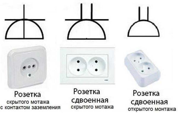
If you look at the images carefully, notice that the conditional image on the right does not have a horizontal line that separates the two parts of the icon. This line indicates that the socket is flush-mounted, i.e. it is necessary to make a hole in the wall for it, install a sub-socket, etc. The variant on the right is for open mounting. A non-conductive substrate is attached to the wall, and the socket itself is mounted on it.
Also note that the lower part of the left schematic is crossed out with a vertical line. This is the protective contact to which the ground is connected. Installation of sockets with grounding is mandatory when turning on complex household appliances such as washing machines, dishwashers, ovens, etc.
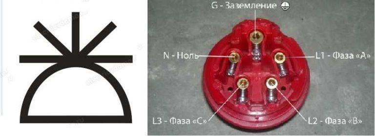
With nothing can not confuse the conventional designation of a three-phase socket (for 380 V). The number of segments sticking up is equal to the number of conductors that are connected to this device: three phases, zero and ground. The total is five.
It happens that the lower part of the image is painted black (dark). This indicates that the outlet is waterproof. Such put on the street, in rooms with high humidity (baths, swimming pools, etc.).
Display of switches
Schematic designation of switches looks like a small-sized circle with one or more L- or T-shaped branches. The branches in the form of the letter G indicate an open-mounted switch and the letter T indicates a flush-mounted switch. The number of taps represents the number of keys on this device.
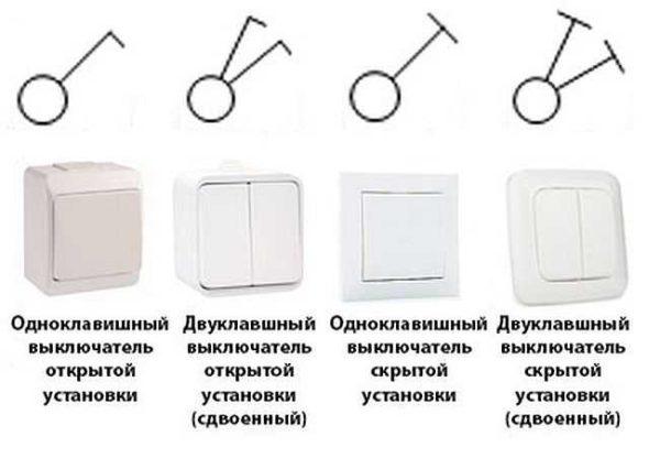
In addition to the usual ones, there can be pass-through switches – for the possibility of turning on/off one light source from several points. To the same small circle on opposite sides draw two letters “G”. This is how the single-key pass-through switch is designated.
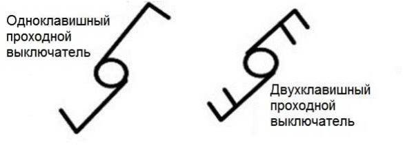
Unlike conventional switches, these two-key models add another bar parallel to the upper one.
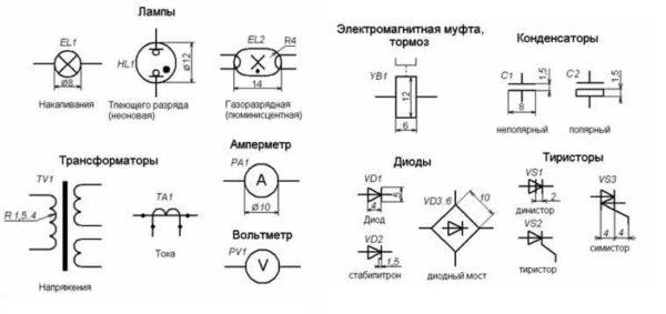
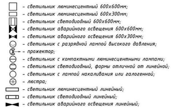
Lamps and lamps
Lamps have their own designations. And there is a difference between daylight (fluorescent) and incandescent lamps. Even the shape and size of lamps are shown on the diagrams. In this case, it is only necessary to memorize how each type of lamp looks on the scheme.
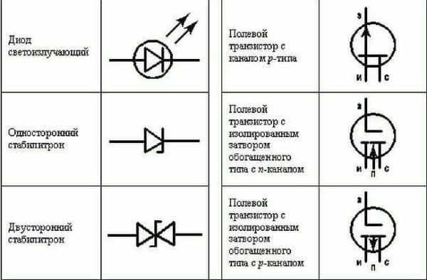
Radio elements
When reading circuit diagrams of devices, it is necessary to know the symbols of diodes, resistors, and other similar elements.

Knowledge of conventional graphic elements will help you read almost any scheme – some device or wiring. The ratings of the required parts are sometimes put next to the image, but in large multi-element schemes they are written in a separate table. In it there are letter designations of circuit elements and ratings.
Letter designations
In addition to the fact that the elements in the schemes have conventional graphic names, they have letter designations, and also standardized (GOST 7624-55).
| Name of the element of the electrical circuit | Letter designation | |
|---|---|---|
| 1 | Switch, controller, switch | В |
| 2 | Electric generator | Г |
| 3 | Diode | Д |
| 4 | Rectifier | Vp |
| 5 | Sound signaling (bell, siren) | Sv |
| 6 | Button | Kn |
| 7 | Incandescent lamp | Л |
| 8 | Electric motor | М |
| 9 | Fuse | Fuse |
| 10 | Contactor, magnetic starter | К |
| 11 | Relay | Р |
| 12 | Transformer (autotransformer) | Tr |
| 13 | Plug connector | Ш |
| 14 | Electromagnet | Em |
| 15 | Resistor | R |
| 16 | Capacitor | С |
| 17 | Inductance coil | L |
| 18 | Control button | Koo |
| 19 | Limit switch | Kv |
| 20 | Choke | Dr |
| 21 | Telephone | Т |
| 22 | Microphone | Mk |
| 23 | Loudspeaker | Gr |
| 24 | Battery (galvanic cell) | Б |
| 25 | Main motor | Dg |
| 26 | Cooling pump motor | Do |
Note that in most cases Russian letters are used, but the resistor, capacitor and inductance coil are labeled with Latin letters.
There is one subtlety in the designation of relays. They come in different types, respectively, are labeled:
- current relay – PT;
- power – PM;
- voltage – PH;
- time – RV;
- resistance – RS;
- indicating – RU;
- intermediate – RP;
- gas – RG;
- with time delay – PTB.
Basically, these are only the most conventional designations in electrical schematics. But most of the drawings and plans you will now be able to understand. If you need to know the images of more rare elements, study GOSTs.

")


