

The problem of protecting the wiring from overloads and leakage currents can be solved with a pair of devices – a circuit breaker and an RCD. But the same problem is solved by a differential circuit breaker, which combines both of these devices in one body. About the correct connection of the differential circuit breaker and its choice and will be discussed further.
Straipsnio turinys
Purpose, technical characteristics and choice
Diffautomat or differential circuit breaker combines the functions of a circuit breaker and RCD. That is, this device alone protects the wiring from overloads, short circuits and leakage current. Leakage current is formed when the insulation is faulty or when touching live elements, that is, it still protects a person from electric shock.
Diffautomats are installed in electrical distribution boards, most often on din-rails. They are put instead of a bunch of automatic circuit breaker + RCD, physically occupy a little less space. How much – depends on the manufacturer and type of execution. And this is their main advantage, which may be in demand when modernizing the network, when the space in the switchboard is limited, and it is necessary to connect a number of new lines.
The second positive moment – saving money. As a rule, difautomat costs less than a pair of “automat + RCD” with similar characteristics. Another positive point – it is necessary to determine only the nominal value of the circuit breaker, and RCD is built in by default with the required characteristics.
The disadvantages are also present: in case of failure of one of the parts of the difautomat will have to change the whole device, and this is more expensive. Also not all models are equipped with flags, by which you can determine the reason for which the device is triggered – due to overload or leakage current, which is fundamentally important in determining the causes.
Characteristics and selection
Since the difautomat combines two devices, it has the characteristics of both of them, and when choosing it, you need to take everything into account. Let’s understand what these characteristics denote and how to choose a differential circuit breaker.
Rated current
This is the maximum current that can withstand for a long time without loss of performance. It is usually indicated on the front panel. Rated currents are standardized and can be 6A, 10A, 16A, 20A, 25A, 32A, 40A, 50A, 63A.
Small nominal values – 10 A and 16 A – put on lighting lines, medium – on powerful consumers and socket groups, and powerful – 40 A and above – mainly used as an input (general) difautomat. It is selected depending on the cross-section of the cable, in the same way as when selecting the rating of the circuit breaker.
Time-current characteristic or type of electromagnetic trip unit
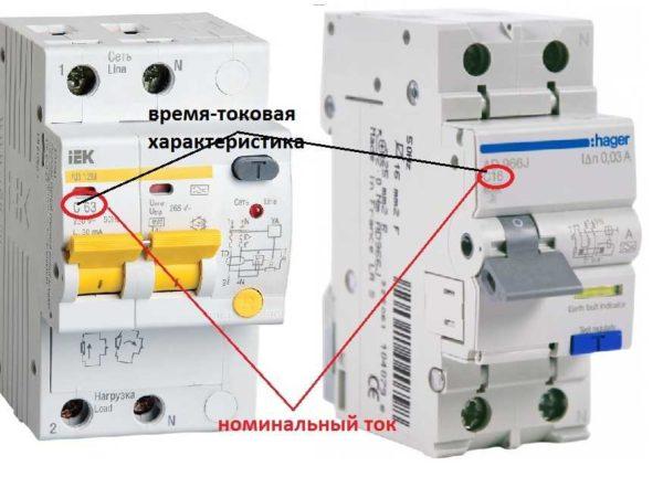
Displayed next to the rating, indicated by the Latin letters B, C, D. Indicates at which overloads relative to the rating the automatic unit trips (to ignore short-term starting currents).
Category B – if the current is exceeded by 3-5 times, C – when the nominal value is exceeded by 5-10 times, type D is disconnected at loads that exceed the nominal value by 10-20 times. In apartments usually put type C, in rural areas you can put B, in enterprises with powerful equipment and large starting currents – D.
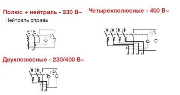
Rated voltage and frequency of the network
For which networks the device is designed – 220 V and 380 V, with a frequency of 50 Hz. There are no others in our retail network, but it is still worth checking.
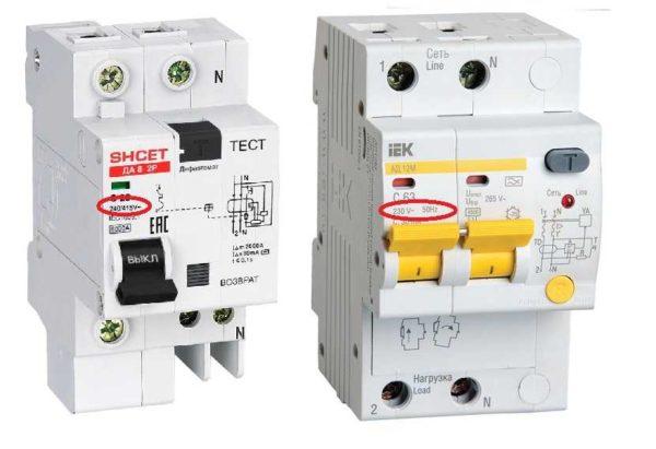
Differential automatic machines can have a double marking – 230/400 V. This indicates that this device can work both in a network of 220 V and 380 V. In three-phase networks, such devices are placed on outlet groups or on individual consumers, where only one of the phases is used.
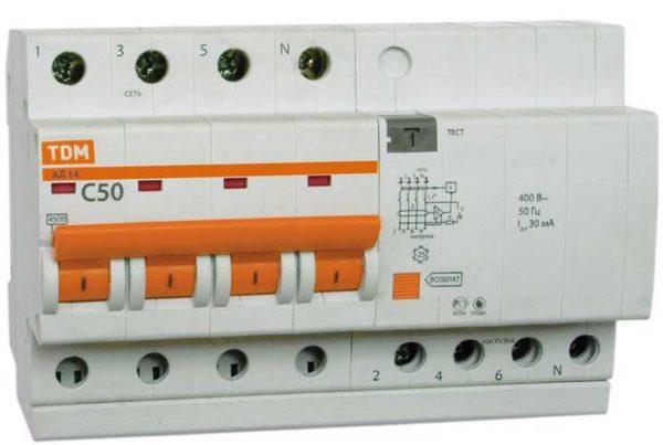
As water difautomats on three-phase networks require devices with four inputs, and they differ significantly in size. It is impossible to confuse them.
Nominal tripping differential current or leakage current (setpoint)
Displays the sensitivity of the device to the leakage currents generated and indicates under which conditions the protection will trip. Only two ratings are used in the home: 10 mA for installation on lines with only one powerful appliance or a consumer that combines two hazards – electricity and water (flow or storage electric water heater, cooktop, oven, dishwasher, etc.).
For lines with a group of outlets and outdoor lighting put difautomata with a leakage current of 30 mA, on the line of lighting inside the house they are not usually put – to save money.
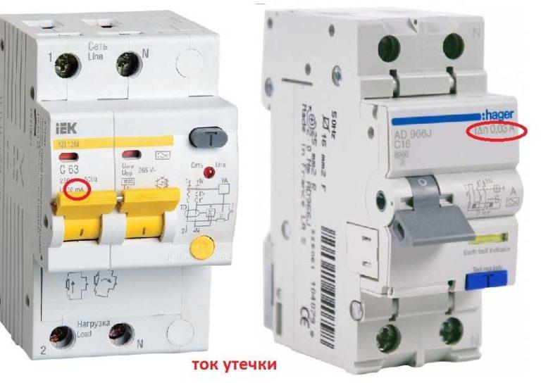
On the device can be written simply the value in milliamperes (as in the photo on the left) or can be applied letter designation of the current setting (in the photo on the right), after which there are digits in amperes (at 10 mA is 0,01 A, at 30 mA digit 0,03 A).
Differential protection class
Indicates what type of leakage currents this device protects against. There are alphabetic and graphic representations. Usually there is an icon, but there can also be a letter (see the table).
| Letter designation | Graphic designation | Deciphering | Field of application |
|---|---|---|---|
| AC |  |
Responds to alternating sinusoidal current. | It is used on lines to which simple appliances without electronic control are connected. |
| А |  |
Responds to sinusoidal alternating current and pulsating direct current. | Used on lines from which electronically controlled appliances are supplied. |
| В |  |
Catches alternating, pulsating, direct and smoothed direct. | Mainly used in production facilities with a wide variety of machinery. |
| S | With 200-300 ms tripping time delay | In complex circuits | |
| G | With a tripping time of 60-80 ms | In complex circuits |
The selection of the class of differential protection of the diphautomata is based on the type of load. If it is a technique with microprocessors, you need class A, on the line of lighting or power supply of simple devices is suitable class AC. Class B in private houses and apartments is rarely put – there is no need to “catch” all types of leakage currents. Connecting a class S and G difautomatic unit makes sense in multi-level protection schemes. They are placed as input, if the scheme further there are other differential tripping devices. In this case, when one of the downstream ones is tripped by the leakage current, the input one will not trip, and the faulty lines will be in operation.
Rated tripping capacity
Indicates the current that the device is able to disconnect in the event of a short-circuit and remain operable. There are several standard ratings: 3000A, 4500A, 6000A, 10 000A.
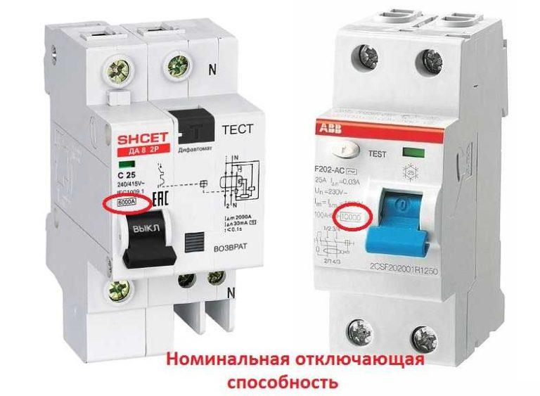
The choice of a difautomat according to this parameter depends on the type of network and on the distance of the substation. In apartments and houses at a sufficient distance from the substation use diphautomats with a breaking capacity of 6000 A, close to the substation put on 10000 A. In rural areas, if the power supply is supplied by “overhead” and in networks that have not been modernized for a long time, 4500 A is sufficient.
On the case this figure is indicated in a square frame. The location of the inscription may be different – depends on the manufacturer.
Current limitation class
Some time must elapse before the short-circuit current reaches its maximum value. The sooner the power is disconnected from the faulted line, the less likely it is that damage will occur. The current limiting class is indicated by numbers from 1 to 3. Class 3 disconnects the line the fastest. So, the choice of difautomat according to this feature is simple: it is desirable to use devices of the third class, but they are expensive, but they remain functional longer. So, if you have the financial ability to put the difautomats of this class.
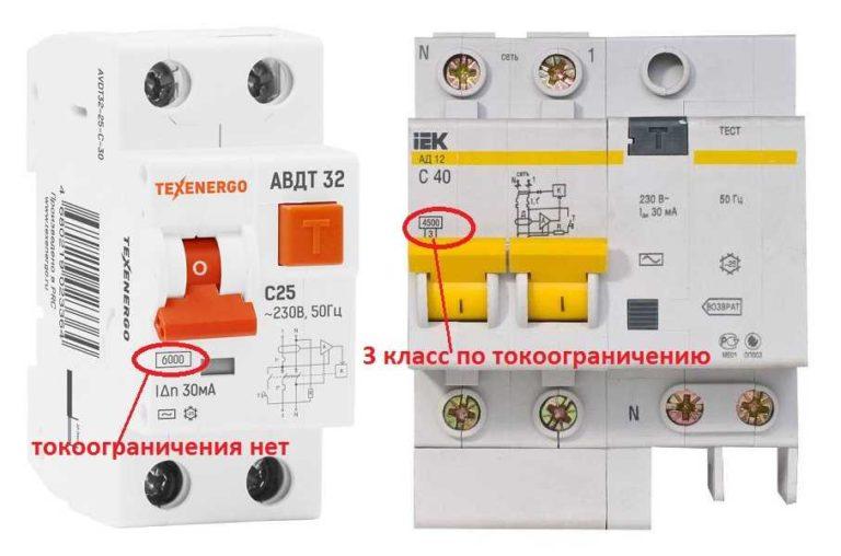
This characteristic is shown on the housing in a small square box next to the rated breaking capacity. It can be on the right (for Legranda) or at the bottom (for most other manufacturers). If you have not found such a mark neither on the case, nor in the passport, then this automatic circuit breaker does not have current limitation.
Temperature mode of use
Most differential circuit breakers are designed to work indoors. They can be operated at temperatures from -5°C to + 35°C. In this case, nothing is put on the housing.
Sometimes shields stand on the street, and ordinary protective devices are not suitable. For such cases, there are produced difautomatic devices with a wider temperature range – from -25°C to +40°C. In this case, a special mark is placed on the housing, which looks a little like an asterisk.
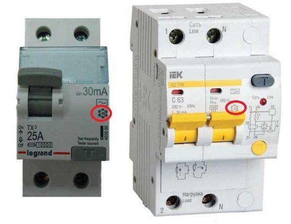
The presence of markers about the cause of tripping
Difautomats not all electricians like to put, because they believe that the bundle “protective automatic circuit breaker + RCD” is more reliable. The second reason – if the device is triggered, it is impossible to determine what caused it: overload, and you just need to turn off some device, or leakage current, and you need to look for where and what happened.
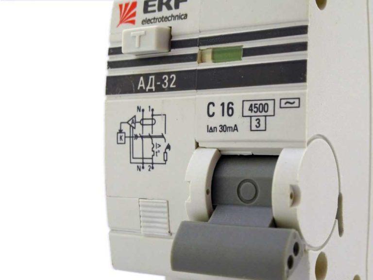
To solve at least the second problem, manufacturers began to make flags that show the reason for the tripping of the device. In some models it is a small pad, by the position of which the cause of tripping is determined.
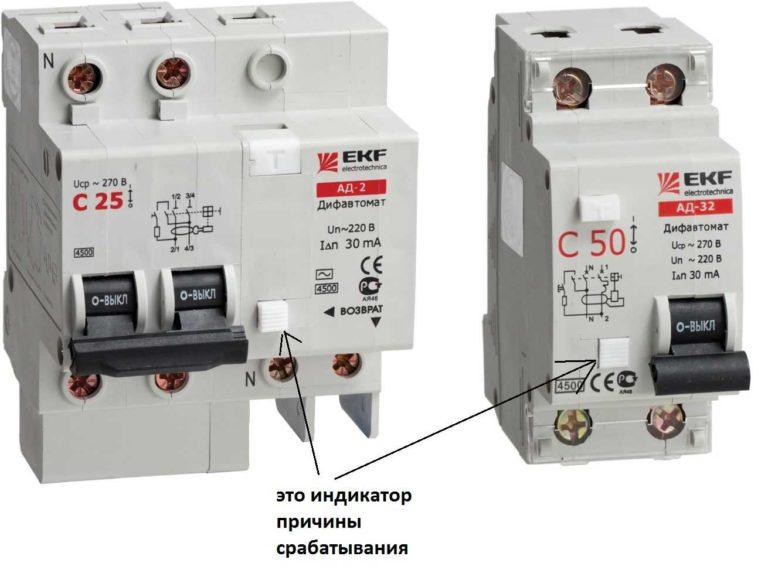
If the tripping was caused by an overload, the indicator remains flush with the housing, as in the photo on the right. If the tripping was caused by a leakage current, the flags protrude some distance from the housing.
Type of construction
There are two types of fault circuit breakers: electromechanical or electronic. Electromechanical ones are more reliable, as they keep working even in case of power failure. That is, if the phase is lost, they can work and disconnect the zero. Electronic for work require power, which is taken from the phase wire and with the loss of phase lose functionality.
Manufacturer and price
In electricity is not worth saving, especially on devices that provide protection for wiring and life. Therefore, it is recommended to always buy components of well-known manufacturers. Lead the market Legrand (Legrand) and Schneider (Schneider), Hager (Hager), but their products are expensive, and a lot of fakes. Not so high prices at IEK (IEK), ABB (ABB), but there are more problems with them. With unknown manufacturers in this case, it is better not to contact, as they are often simply inoperable.
The choice is actually not so small, even if you limit yourself to only these five firms. Each manufacturer has several lines, which differ in price, and significantly. To understand what the difference is, you need to look carefully at the technical characteristics. The price is influenced by each of them, so carefully study all the data before buying.
How to connect a difautomat
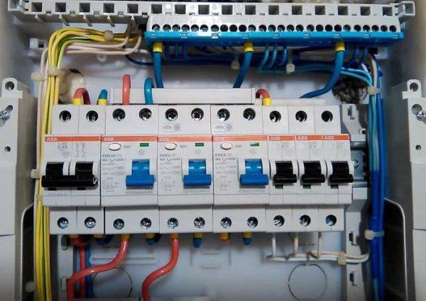
Let’s start with the methods of installation and the order of connection of conductors. Everything is very simple, there are no special difficulties. In most cases, it is mounted on a dinreika. For this purpose, there are special protrusions that hold the device in place.
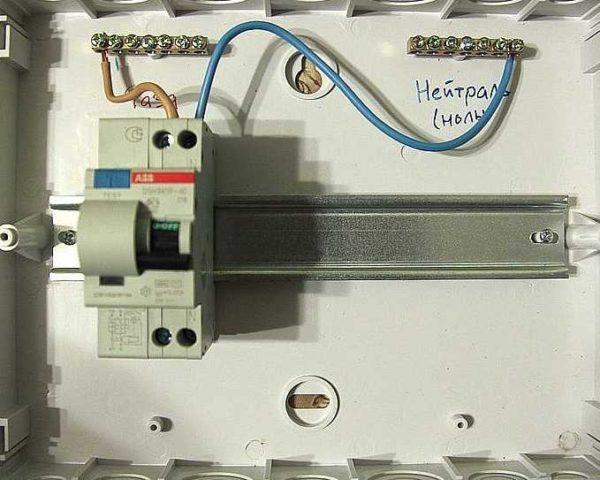
Electrical connection
Connection of the difautomatic unit to the power supply is carried out with insulated wires. The cross-section is selected based on the nominal value. Usually the line (power supply) is connected to the upper sockets – they are signed with odd numbers, the load – to the lower ones – signed with even numbers. Since the phase and zero are connected to the differential automatism, in order not to confuse, the sockets for “zero” are signed with the Latin letter N.
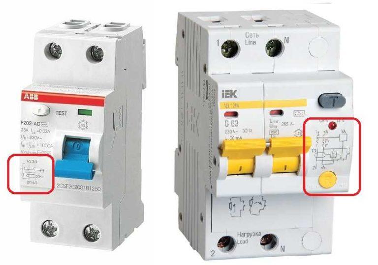
In some rulers it is possible to connect the line in both upper and lower sockets. An example of such a device in the photo above (left). In this case, the numbering is written on the diagram through a fraction – 1/2 at the top and 2/1 at the bottom, 3/4 at the top and 4/3 at the bottom. This means that it does not matter whether the line is connected from above or below.
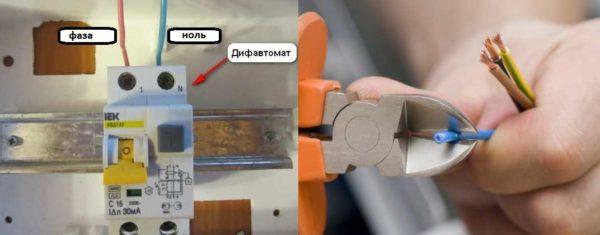
Before connecting the line, the insulation is stripped from the wires at a distance of about 8-10 mm from the edge. On the desired terminal slightly loosen the fixing screw, insert the conductor, the screw is tightened with a sufficiently large force. Then pull the conductor several times to make sure that the contact is normal.
Functionality test
After you have connected the difautomatic unit, supplied power, it is necessary to check the operability of the system and the correctness of the installation. To begin with, we test the unit itself. For this purpose there is a special button signed “Test” or simply with the letter T. After having switched the switches to the working state, we press this button. At that, the unit should “kick out”. This button artificially creates a leakage current, so that we have checked the operability of the automatic circuit breaker. If there was no tripping – it is necessary to check the correctness of connection, if everything is correct, the device is defective.
The next check is to connect a simple load to each socket. This will verify that the outlet groups are properly disconnected. And lastly – alternately turn on household appliances, which are connected to separate power lines.
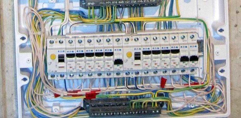
Schemes
When developing a scheme of electrical wiring in an apartment or house, there can be many options. They may differ in convenience and reliability of operation, the degree of protection. There are simple options that require a minimum of costs. They are usually realized in small networks. For example, in cottages, in small apartments with a small number of household appliances. In most cases, it is necessary to put a large number of devices that ensure the safety of wiring and protect against electrocution of people.
Simple circuit
It does not always make sense to install a large number of protective devices. For example, in a seasonal cottage, where there are only a few outlets and lighting, it is enough to put just one difautomatic at the entrance, from which the groups of consumers – outlets and lighting – through automatic machines will go separate lines.
This scheme will not require large costs, but if there is a leakage current on any of the lines, the difautomat will work, de-energizing everything. Until the causes are clarified and eliminated, there will be no light.
More reliable protection
As already mentioned, separate difautomatic devices are put on “wet” groups. These include the kitchen, bathroom, outdoor lighting, as well as appliances that use water (except for the washing machine). This way of building the system gives a higher degree of safety and better protects the wiring, equipment and person.
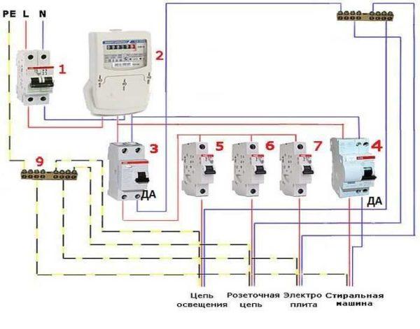
Realization of this method of wiring device will require more material costs, but the system will work more reliably and stably. Since when one of the protective devices is triggered, the rest of the system will remain operational. Such a connection of a difautomatic is used in most apartments and in small houses.
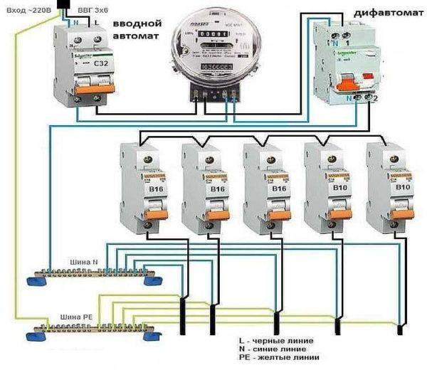
Selective schemes
In branched power supply networks, there is a need to make the system even more complex and expensive. In such a variant after the meter an input differential circuit breaker of class S or G is installed. Further on each group has its own automatic circuit breaker, and if necessary, they are also put on individual consumers. Connection of a differential automatic for this case, see the photo below.
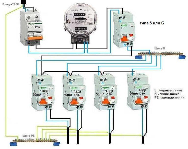
With this system construction, when one of the linear devices is triggered, all the other devices will remain in operation, since the input automatic differential disconnection machine has a delay in triggering.
The main mistakes of connection of differential circuit breakers
Sometimes after connecting a differential circuit breaker, it does not turn on or cuts out when any load is connected. This means that something is done wrong. There are several typical errors that are encountered when independently assembling the switchboard:
- The wires of the protective zero (ground) and working zero (neutral) are combined somewhere. With such an error, the switch does not turn on at all – the levers are not fixed in the upper position. You will have to look for where the ground and neutral are united or mixed up.
- Sometimes, when connecting the diphautomata zero on the load or on the below located automatic machines is taken not from the output of the device, but directly from the zero bus. In this case, the switches become in the working position, but when trying to connect the load, they are instantly disconnected.
- The zero is not taken from the output of the switch disconnector to the load, but goes back to the busbar. Zero to the load is also taken from the busbar. In this case, the switches are in the working position, but the “Test” button does not work and when trying to turn on the load, the load is disconnected.
- The zero connection is mixed up. From the neutral bus, the wire should go to the corresponding input marked with the letter N, which is at the top, not down. From the bottom zero terminal, the wire should go to the load. The symptoms are similar: the breakers turn on, the “Test” does not work, when the load is connected, tripping occurs.
- If there are two difautomats in the circuit, the neutral wires are mixed up. With this error both devices are switched on, “Test” works on both devices, but when any load is switched on, both breakers are tripped at once.
- If there are two automatic machines, the zeros coming from them somewhere further connected. In this case, both breakers are energized, but when you press the “test” button of one of them, two devices are knocked out at once. The same situation occurs when switching on any load.
Now you can not only choose and connect the differential protection circuit breaker, but also understand why it kicks out, what exactly went wrong and independently correct the situation.

")


