

Electricity is an area where everything needs to be done correctly and thoroughly. In this regard, many people prefer to figure things out for themselves rather than trust outsiders. One of the key points is the connection of wires in the junction box. On the quality of work depends firstly, the correctness of the system, and secondly – safety – electrical and fire.
Isi artikel
What is a junction box
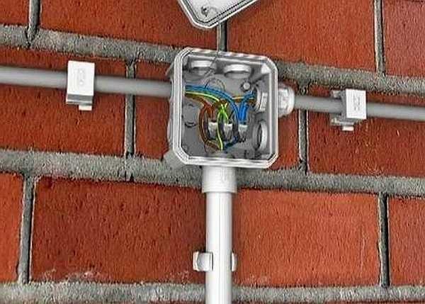
From the electrical panel wires are distributed to the rooms in the house or apartment. In each room, as a rule, there is not one connection point: several outlets and a switch are exactly. To standardize the ways of connecting wires and collect them in one place, use junction boxes (they are also sometimes called branching or broaching). They wind up cables from all connected devices, the connection of which occurs inside the hollow body.
In order not to look for wiring in the process of the next repair, it is laid according to certain rules, which are prescribed in the PUE – Rules of Electrical Installations.
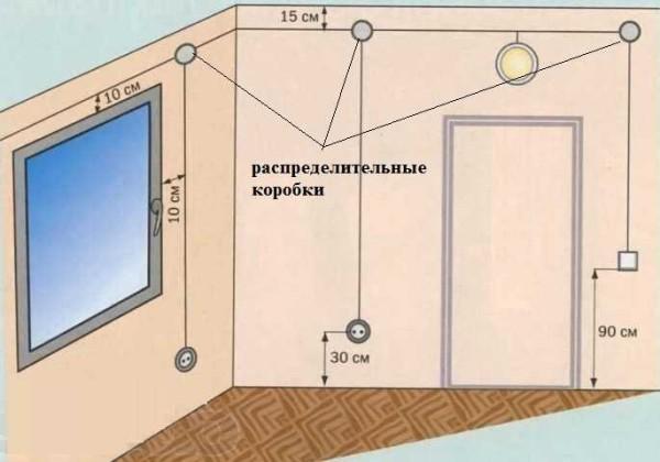
One of the recommendations is to conduct all connections and branches of wires in the junction box. Therefore, the wires run along the top of the wall, at a distance of 15 cm from the ceiling level. Reaching the place of branching, the cable is lowered vertically downwards. In the place of branching is installed junction box. In it and there is a connection of all the wires according to the required scheme.
According to the type of installation switchboxes are internal (for concealed installation) and external. Under the internal in the wall make a hole in which the box is built in. With this installation, the cover is at the same level with the finishing material. Sometimes in the process of repair, it is closed with finishing materials. However, such installation is not always possible: the thickness of the walls or finishing does not allow. Then a box for external installation is used, which is attached directly to the surface of the wall.
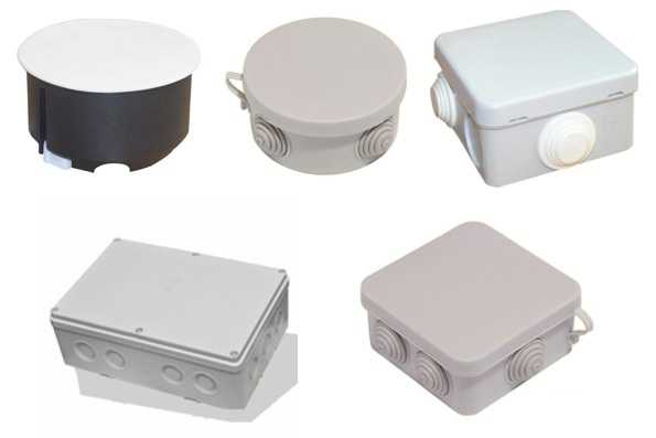
In shape, the junction box can be round or rectangular. The leads are usually four, but there can be more. The leads have threads or connectors, to which it is convenient to attach a corrugated hose. After all, it is in the corrugated hose or plastic pipe is more convenient to lay wires. In this case, replacing a damaged cable will be very easy. First disconnect it in the junction box, then from the consumer (outlet or switch), pull and pull out. In its place, tighten a new one. If you lay the old-fashioned way – in a groove, which then plastered – to replace the cable will have to chisel the wall. So this is the recommendation of the PUE, which is definitely worth listening to.
What in general give junction boxes:
- Increased repairability of the power supply system. Since all connections are available, it is easy to identify the area of damage. If the conductors are laid in cable channels (corrugated hoses or pipes), it will be easy to replace the damaged area.
- Most electrical problems occur in the connections, and in this version of installation, they can be periodically inspected.
- Installation of junction boxes increases the level of fire safety: all potentially dangerous places are located in certain places.
- Requires less money and labor than laying a cable to each of the outlets.
Ways of connecting wires
In the box, conductors can be connected in different ways. Some of them are more difficult to realize, others are easier, but with proper execution, all of them provide the required reliability.
Twisting
The most popular method among folk craftsmen, but the most unreliable. It is not recommended by the PUE for use, as it does not provide proper contact, which can lead to overheating and fire. This method can be used as a temporary, for example, to test the performance of the assembled circuit, with the obligatory subsequent replacement with a more reliable one.
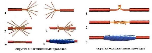
Even if the connection is temporary, it is necessary to do everything according to the rules. Methods of twisting stranded and single-core conductors are similar, but have some differences.
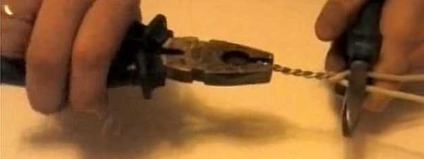
When twisting stranded wires, the order of actions is as follows:
- insulation is stripped by 4 cm;
- conductors are untwisted by 2 cm (pos. 1 on the photo);
- the conductors are connected up to the junction of untwisted conductors (item 2);
- the conductors are twisted with fingers (item 3);
- the twist is tightened with pliers or pliers (item 4 on the photo);
- insulated (insulating tape or heat-shrink tubing put on before the connection).
The connection of wires in the junction box with a single conductor by twisting is easier. Cleaned of insulation conductors are crossed and twisted with fingers along the entire length. Then take a tool (pliers and pliers, for example). In one clamp the conductors near the insulation, the second hard twist the conductors, increasing the number of turns. The place of connection is isolated.
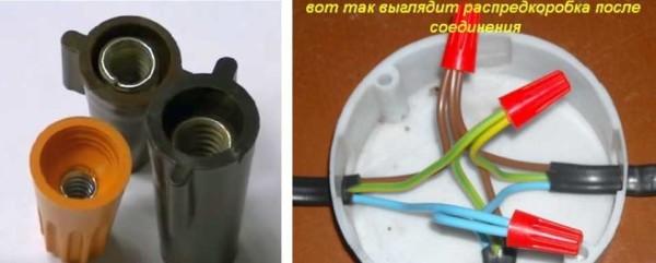
Twisting with mounting caps
It is even easier to make a twist with the use of special caps. With their use, the connection is more reliably insulated, the contact is better. The outer part of such a cap is molded from plastic, which does not support combustion, and a metal conical part with a thread is inserted inside. This insert provides a larger contact surface, improving the electrical performance of the connection. This is a great way to connect two (or more) wires without soldering.
Twisting wires using caps is even easier: 2 cm of insulation is removed and the wires are slightly twisted. A cap is put on them, turned several times with force until the metal is inside the cap. Everything, the connection is ready.
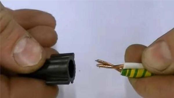
Caps are selected depending on the cross-section and number of conductors that need to be connected. This method is more convenient: it takes up less space than the usual twisting, everything is laid more compactly.
Soldering
If there is a soldering iron in the house, and you know how to handle it at least a little, it is better to use soldering. Before twisting wires tin: apply a layer of rosin or soldering flux. A heated soldering iron is dipped in rosin, and run several times over the part stripped of insulation. A characteristic reddish-colored patina appears on it.
After that, the wires are twisted as described above (twist), then take tin on the soldering iron, heat the twist until the molten tin does not flow between the coils, enveloping the connection and ensuring good contact.
This method installers do not like: it takes a lot of time, but if the connection of wires in the junction box do for yourself, do not spare time and effort, but will sleep well.
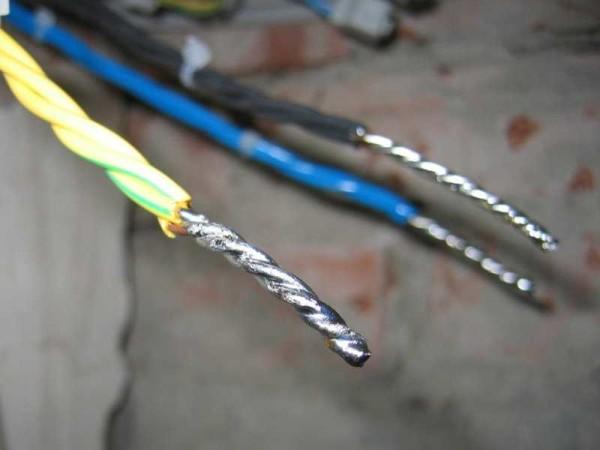
Welding wires
If there is an inverter welding machine, you can use the connection by welding. This is done over twisting. Set the welding current on the machine:
- for a cross-section of 1.5 mm2about 30 A,
- for a cross-section of 2.5 mm2 – 50 A.
Use a graphite electrode (this is for welding copper). Grounding pliers carefully cling to the upper part of the twist, to it from below bring the electrode, briefly touch, achieving the ignition of the arc, and remove. Welding takes place in a fraction of a second. After cooling down, the joint is insulated. The process of welding wires in the junction box, see the video.
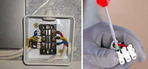
Terminal blocks
Another connection of wires in the junction box – with the help of terminal blocks – terminal blocks, as they are also called. There are different types of pads: with clamps and screws, but, in general, the principle of their device is the same. There is a copper sleeve/plate and wire fastening system. They are arranged so that by inserting two/three/four conductors in the right place, you connect them securely. The installation is very simple.
Screw terminal blocks have a plastic housing in which the contact plate is fixed. They are of two types: with hidden contacts (new) and with open – old-style. In either of them in the socket is inserted cleaned of insulation conductor (length up to 1 cm) and clamped with a screw and a screwdriver.
Their disadvantage is that it is not very convenient to connect a large number of wires in them. Contacts are located in pairs, and if you need to connect three or more wires, you have to squeeze two wires into one socket, which is difficult. But they can be used in branches with significant current consumption.
Another type of terminal blocks are Vago terminal blocks. These are pads for quick installation. Basically two types are used:
The peculiarity of these terminal blocks is that they can be operated only at low currents: up to 24 A with a copper wire cross-section of 1.5 mm, and up to 32 A with a cross-section of 2.5 mm. When connecting loads with high current consumption, the connection of the wires in the junction box must be done in a different way.
Crimping
This method is possible with special pliers and a metal sleeve. The sleeve is put on the twist, it is inserted into the pliers and clamped – pressed. This method is just suitable for lines with a large ampere load (like welding or soldering). See the video for details. It even collected a model of a junction box so it will be useful.
Basic wiring diagrams
Know how to make the connection of wires in the junction box is not all. It is necessary to understand what conductors to connect.
How to connect sockets
As a rule, the outlet group is a separate line. In this case, everything is clear: you have three cables with three (or two) conductors in the box. The coloring can be such as in the photo. In this case, usually brown is the phase wire, blue – zero (neutral), and yellow-green – ground.
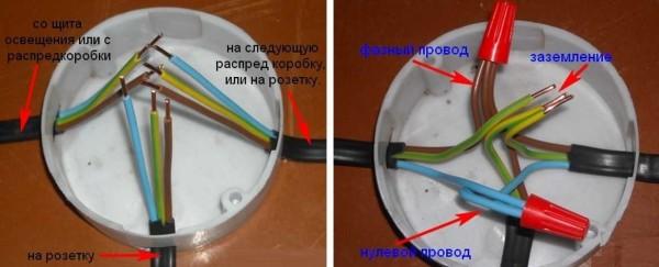
In another standard, the colors can be red, black and blue. In this case, the phase is red, blue – neutral, green – ground. In either case, the wires are assembled by color: all of the same color into one group.
Then they are folded, pulled, cut to be the same length. Do not cut short, leave a reserve of at least 10 cm, so that if necessary you can redo the connection. Then the conductors are connected using the chosen method.
If the wires are used only two (in old houses there is no zazmleniya), everything is exactly the same, but the connections are two: phase and neutral. By the way, if the wires are the same color, preliminarily find the phase (probe or multimeter) and mark it, at least by winding a piece of tape on the insulation.
Connecting a single-key switch
If there is a switch, the matter is more complicated. There are also three groups, but their connection is different. There are
- input – from another junction box or from the switchboard;
- from a chandelier;
- from a switch.
How should the circuit work? Power – “phase” – goes to the key of the switch. From its output is fed to the chandelier. In this case, the chandelier will burn only when the contacts of the switch are closed (position “on”). This type of connection is shown in the photo below.
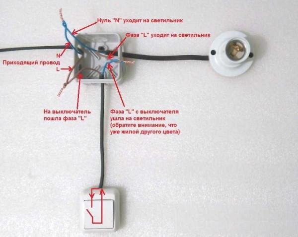
If you look carefully, so it turns out: the phase light wire goes to the switch. Goes from another contact, but already blue (do not confuse) and connects to the phase wire, which goes to the chandelier. Neutral (blue) and ground (if mains) are twisted directly.
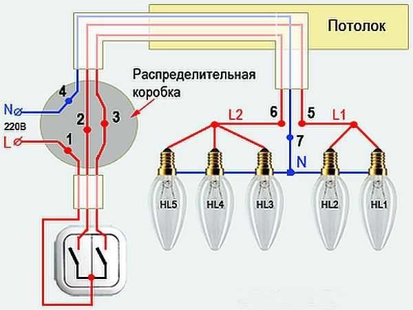
Connecting a two-key switch
Connection of wires in the junction box in the presence of a two-key switch is a little more complicated. The peculiarity of this scheme is that to the switch for two groups of lamps, a three-core cable should be laid (in the scheme without grounding). One wire is connected to the common contact of the switch, the other two – to the outputs of the keys. It is necessary to remember what color conductor is connected to the common contact.
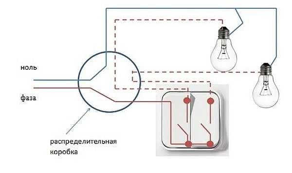
In this case, the phase that came in is connected to the common contact of the switch. Blue wires (neutral) from the input and two lamps is simply twisted all three together. The wires that remain are the phase wires from the lamps and the two wires from the switch. Here and connect them in pairs: one wire from the switch to the phase of one lamp, the second output – to another lamp.
Once again about the connection of wires in the junction box with a two-key switch in video format.
")


Connecting wires in a junction box can feel tricky, but it’s actually super fun! I remember tackling it for the first time; I felt like a DIY pro! Just remember to match colors and twist them right! Totally nailed it and was buzzing with pride afterward!