

Contactors or magnetic starters are used to supply power to motors or any other devices. Devices designed for frequent switching on and off of power. The wiring diagram of the magnetic starter for single-phase and three-phase network and will be considered further.
Contenu de l'article
Contactors and starters – what is the difference
Both contactors and starters are designed to close/open contacts in electrical circuits, usually – power. Both devices are assembled on the basis of an electromagnet, can work in DC and AC circuits of different power – from 10 V to 440 V DC and up to 600 V AC. They have:
- some number of working (power) contacts, through which voltage is supplied to the connected load;
- a certain number of auxiliary contacts – for the organization of signal circuits.
So what is the difference? What are the differences between contactors and starters. First of all, they differ in the degree of protection. Contactors have powerful arc suppression chambers. Hence, there are two other differences: due to the presence of arc suppressors contactors have a large size and weight, and are used in circuits with high currents. For small currents – up to 10 A – are produced exclusively starters. They, by the way, for large currents are not produced.
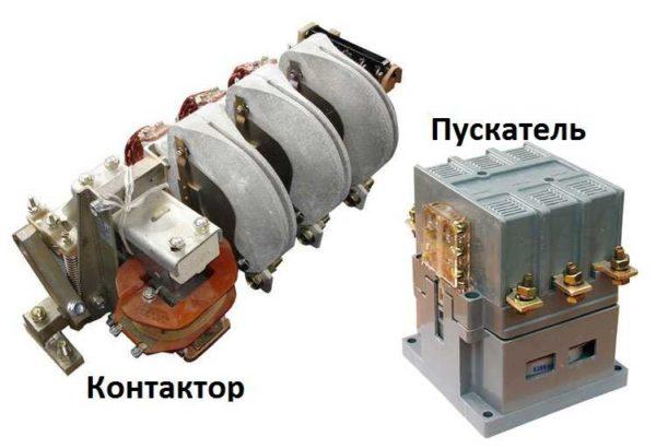
There is another design feature: starters are produced in a plastic case, they have only the contact pads outside. Contactors, in most cases, do not have a housing, so must be installed in protective cases or boxes that protect against accidental contact with live parts, as well as from rain and dust.
In addition, there is some difference in purpose. Starters are designed to start asynchronous three-phase motors. Therefore, they have three pairs of power contacts – to connect the three phases, and one auxiliary, through which the power continues to be supplied to run the motor after the “start” button is released. But since this algorithm of operation is suitable for many devices, they connect through them a variety of devices – lighting circuits, various devices and appliances.
Apparently because the “stuffing” and functions of both devices are almost the same, in many price lists starters are called “small-sized contactors”.
Dispositif et principe de fonctionnement
To better understand the wiring diagrams of the magnetic starter, it is necessary to understand its device and principle of operation.
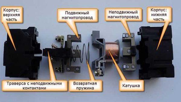
The basis of the starter is a magnetic conductor and an inductance coil. The magnetoconductor consists of two parts – movable and fixed. They are made in the form of letters “SH” set “legs” to each other.
The lower part is fixed to the housing and is stationary, the upper part is spring-loaded and can move freely. A coil is installed in the slot of the lower part of the magnet core. Depending on how the coil is wound, the diverter switch rating changes. There are coils for 12 V, 24 V, 110 V, 220 V and 380 V. There are two groups of contacts on the top of the magnetic core – movable and fixed.
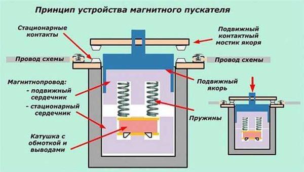
In the absence of power supply, the springs push off the upper part of the magnetic core, the contacts are in the initial state. When voltage appears (the start button is pressed, for example), the coil generates an electromagnetic field, which attracts the upper part of the core. At the same time, the contacts change their position (picture on the right).
When the voltage is lost, the electromagnetic field also disappears, the springs push the moving part of the magnetic core upwards, and the contacts return to their original state. This is the principle of operation of the electromagnetic starter: when voltage is applied, the contacts close, when voltage is lost, they open. Any voltage can be applied to the contacts and connected to them, either DC or AC. It is important that its parameters are not higher than those declared by the manufacturer.
There is another nuance: the contacts of the starter can be of two types: normally closed and normally open. Their principle of operation follows from their names. Normally closed contacts are disconnected when actuated, normally open contacts are closed. For power supply, the second type is used, it is the most common.
Schemes for connecting a magnetic starter with a coil for 220 V
Before we go to the schemes, let’s understand what and how these devices can be connected. Most often, two buttons are required – “start” and “stop”. They can be made in separate housings, or there can be a single housing. This is the so-called pushbutton post.
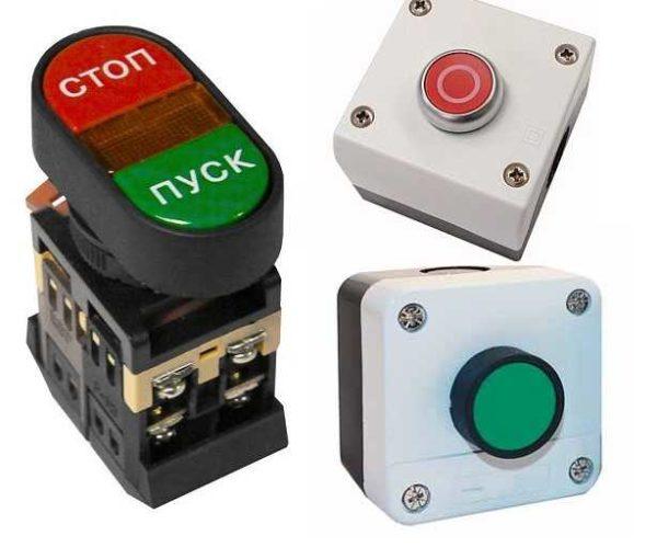
With separate buttons everything is clear – they have two contacts each. Power is supplied to one of them, from the second one it goes out. In the post there are two groups of contacts – two for each button: two for start, two for stop, each group on its own side. There is also usually a terminal for ground connection. Nothing complicated either.
Connecting the starter with a 220 V coil to the network
Actually, there are many options for connecting contactors, we will describe a few. The scheme for connecting a magnetic starter to a single-phase network is more simple, so let’s start with it – it will be easier to understand further.
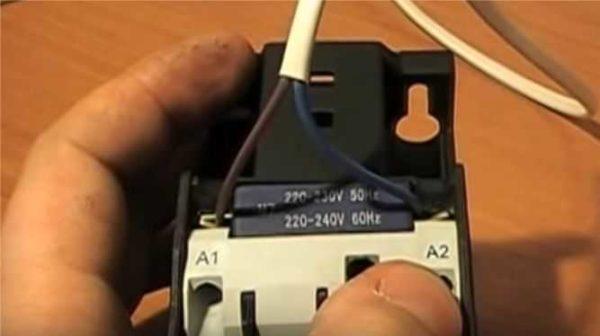
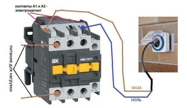
Power, in this case, 220 V, polazhayutsya on the coil leads, which are labeled A1 and A2. Both of these pins are located in the upper part of the case (see photo).
If you connect a cord with a plug (as on the photo) to these contacts, the device will be in operation after the plug is inserted into the socket. To the power contacts L1, L2, L3 can be supplied any voltage, and it can be removed when the starter is triggered from the contacts T1, T2 and T3, respectively. For example, the inputs L1 and L2 can be supplied with a constant voltage from the battery, which will power some device, which should be connected to the outputs T1 and T2.
When connecting a single-phase power supply to the coil, it is not important on which output to supply zero, and on which – phase. You can switch wires. Even more often the phase is fed to A2, because for convenience this contact is taken out on the bottom side of the case. And in some cases it is more convenient to use it, and the “zero” is connected to A1.
But, as you realize, such a scheme for connecting a magnetic starter is not particularly convenient – you can also directly feed the conductors from the power source, having built an ordinary switch. But there are much more interesting options. For example, you can supply power to the coil through a time relay or light sensor, and to the contacts to connect the power line of street lighting. In this case, the phase is connected to the contact L1, and zero can be taken by connecting to the appropriate connector of the coil output (in the photo above it is A2).
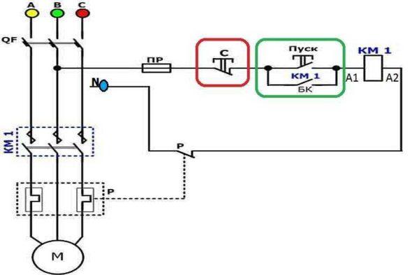
Scheme with “start” and “stop” buttons
Magnetic starters are most often put to turn on the electric motor. It is more convenient to work in this mode if there are buttons “start” and “stop”. They are sequentially included in the phase supply circuit to the output of the magnetic coil. In this case, the circuit looks like the figure below. Note that
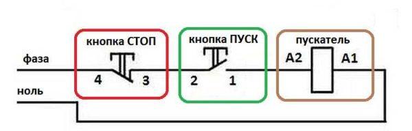
But with this method of switching on the starter will be in operation only for as long as the “start” button is held, and this is not what is required for long-term operation of the motor. Therefore, a so-called self pick-up circuit is added to the circuit. It is realized by means of auxiliary contacts on the starter NO 13 and NO 14, which are connected in parallel with the start button.
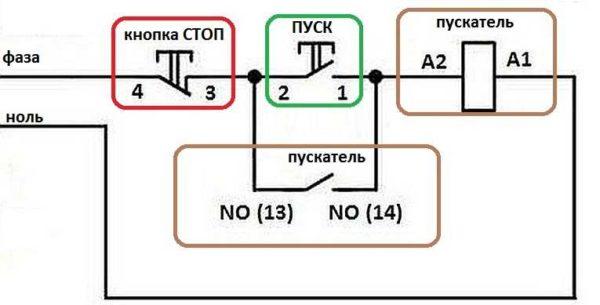
In this case, after returning the START button to the initial state, power continues to flow through these closed contacts, since the magnet is already attracted. And power is supplied until the circuit is broken by pressing the “stop” key or by triggering a thermal relay, if there is one in the circuit.
Power for the motor or any other load (phase from 220 V) is supplied to any of the contacts marked with the letter L, and is removed from the contact under it marked T.
It is shown in detail in what sequence it is better to connect the wires in the following video. The whole difference is that not two separate pushbuttons are used, but a pushbutton post or pushbutton station. Instead of a voltmeter, you will be able to connect a motor, a pump, lighting, any appliance that operates from the 220V network.
Connecting an induction motor for 380 V through a starter with a coil for 220 V
This scheme differs only in that it is connected to the contacts L1, L2, L3 three phases and also three phases go to the load. On the coil of the starter – contacts A1 or A2 – is wound one of the phases. In the picture it is phase B, but most often it is phase C as it is less loaded. The second contact is connected to the neutral wire. A jumper is also installed to maintain power supply to the coil after releasing the START button.
As you can see, the scheme is practically unchanged. Only in it a thermal relay was added, which will protect the motor from overheating. The order of assembly – in the following video. Only the assembly of the contact group differs – all three phases are connected.
Reversible scheme for connecting the electric motor through starters
In some cases, it is necessary to provide rotation of the motor in both directions. For example, for the operation of a winch, in some other cases. Changing the direction of rotation is due to the reversal of phases – when connecting one of the starters two phases must be reversed (for example, phases B and C). The scheme consists of two identical starters and a push-button unit, which includes a common “Stop” button and two buttons “Back” and “Forward”.
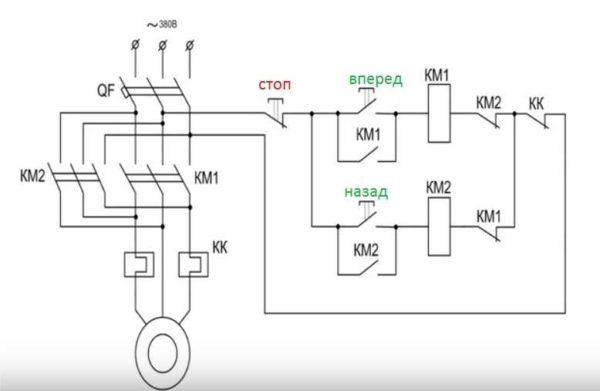
To improve safety, a thermal relay is added, through which two phases pass, the third is fed directly, since the protection of two is more than enough.
Starters can be with a coil for 380 V or 220 V (indicated in the characteristics on the cover). If it is 220 V, one of the phases (any) is fed to the coil contacts, and the second phase is fed “zero” from the panel. If the coil is 380 V, any two phases are fed to it.
Also note that the wire from the trigger (right or left) is not fed directly to the coil, but through the permanently closed contacts of another starter. KM1 and KM2 contacts are shown next to the starter coil. In this way an electrical interlock is realized, which prevents two contactors from being energized at the same time.
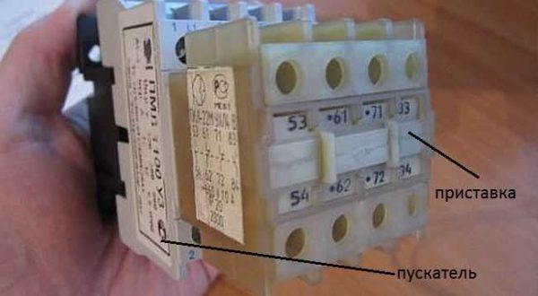
Since not all starters have normally closed contacts, it is possible to take them by installing an additional block with contacts, which is also called a contact attachment. This attachment is snapped into special holders, its contact groups work together with the groups of the main body.
The following video realizes the connection scheme of a magnetic starter with reversing on an old stand using old equipment, but the general order of actions is clear.
 ?")


Connecting a magnetic starter is pretty straightforward. Just make sure to turn off the power first. I once wired one up for my garage compressor. Follow the diagrams, connect the wires right, and you’ll be good to go. Double-check your connections to avoid any hiccups!
Connecting a magnetic starter can be tricky but rewarding. I remember when I first installed one at home. Just make sure you understand the wiring diagram and double-check your connections. It’s all about that smooth flow of electricity! Safety first, though—always turn off the power before getting started.