
")
The current electricity prices make you think about saving money where you never thought about it before. For example, lighting on the stairs. It doesn’t matter whether it’s in a private or multi-storey building – you still have to pay. In the past, you just left the light on. Today you think about turning it off, but running up/down is no fun either. Turns out there is a solution. To keep the lights from being on all the time, there are circuits to control the lights from multiple locations. That is, one or more lights can be turned on and off from several locations. Switches for this need special switches. They are called pass-through switches. Sometimes there are names “duplicating” or “flip”. All these are one type of electrical equipment. They differ from the usual large number of contacts. Accordingly, and the connection scheme of the feedthrough switch is more complicated. Nevertheless, it is possible to understand.
Contents of the article
How does the feed-through switch looks and works?
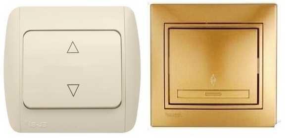
If we talk about the front side, the only difference is a barely noticeable arrow on the up and down keys.
If we talk about the electrical scheme, everything is also simple: in ordinary switches there are only two contacts, in through switches (also called flip switches) there are three contacts, two of which are common. In the scheme is always two or more of these devices, here with the help of these common wires they are switched.
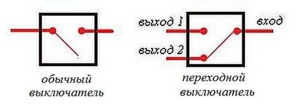
The principle of operation is simple. By changing the position of the key, the input is connected to one of the outputs. So these devices have only two working positions:
- input is connected to output 1;
- input is connected to output 2.
There are no other intermediate positions. This is what makes everything work. Because the contact switches from one position to another, electricians believe it is more correct to call them “switches”. So a feedthrough switch is also this device.
To avoid relying on the presence or absence of arrows on the keys, you need to inspect the contact part. Branded products should have a diagram on them, allowing you to understand what type of equipment you have in your hands. It is definitely there on the products of firms Lezard (Lezard), Legrand (Legrand), Viko (Viko). On Chinese copies they are often absent.
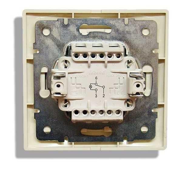
If there is no such scheme, look at the terminals (copper contacts in the holes): they should be three. But by no means always on inexpensive copies, the terminal that stands alone is the input. Often they are mixed up. To find where the common contact is, it is necessary to dial the contacts with each other at different positions of the key. Do this necessarily, otherwise nothing will work, and the device itself may burn out.
You will need a tester or a multimeter. If you have a multimeter, put it in sound mode – it beeps when there is a contact. If you have an arrow tester, probe for a short circuit. Put the probe on one of the contacts, find with which of the two it rings (the device beeps or the arrow shows a short circuit – deviates to the right as far as it will go). Without changing the position of the feeler gauge, change the position of the key. If the short circuit is gone, one of these two is common. Now it remains to check which one. Without changing the key, move one of the probes to the other contact. If there is a short-circuit, the contact from which the probe was not moved is the common (it is the input).
It may become clearer if you watch the video on how to find the input (common contact) for a feedthrough switch.
How to connect the cooktop is written here, and about installation and turning on the water heater – in this article.
Scheme for connecting a pass-through switch from two places
Such a scheme is convenient in a two-story house on the stairs, in a pass-through room, in a long corridor. You can apply it in the bedroom – to turn off the overhead light at the entrance and near the bed (how many times did you have to get up to turn it on/off?).
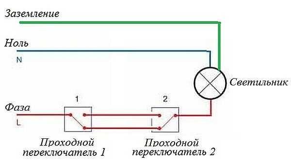
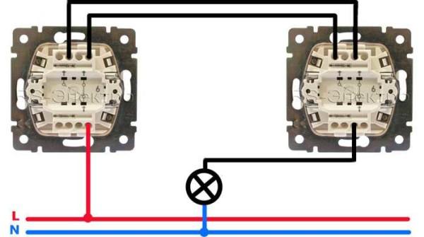
Zero and ground (if available) are brought directly to the light fixture. Phase is fed to the output of the first switch, the input of the second is wound up on a free wire of the luminaire, the outputs of the two devices are connected to each other.
Looking at this scheme, it is easy to understand how the feed-through switch works. In the position shown in the figure, the luminaire is on. By pressing the key of either device, the circuit is broken. Similarly, in the off position, by moving any of them to another position we will close the circuit through one of the jumpers and the lamp will light up.
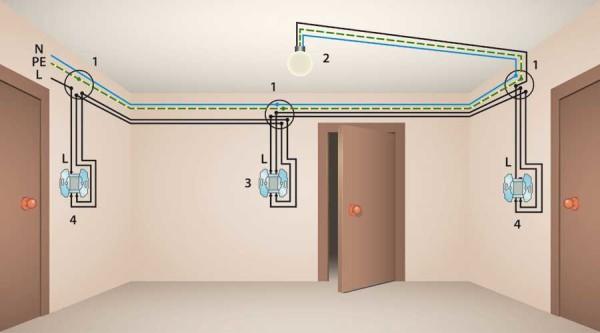
To make it clearer what and what to connect, how to lay wires, we will give some images.
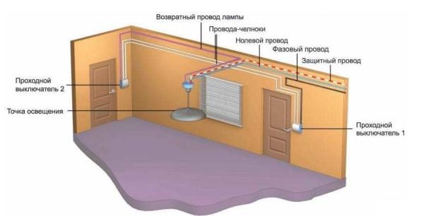
If we talk about the room, then you need to lay the wires approximately as in the photo below. According to modern rules, they should all be at a distance of 15 cm from the ceiling. They can be laid in mounting boxes or trays, the ends of the wires are wound in the mounting boxes. This is convenient: if necessary, you can replace a broken wire. Also, according to the latest norms, all connections are made only in mounting boxes and with the help of contactors. If you make twists, it is better to solder them, and on top of them well wrapped with duct tape.
The return wire of the lamp is connected to the output of the second switch. White indicates the wires connecting the outputs of both devices.
How to connect everything in the terminal box is described in the video.
How to connect the chandelier yourself read here.
Scheme for 3 points
To be able to turn on/off the light from three places, you need to buy a cross (cross) switch to two switches. From those described earlier, it differs in the presence of two inputs and two outputs. It switches a pair of contacts at once. How everything should be organized, see the figure. If you have sorted out what is above, it is easy to understand this one.
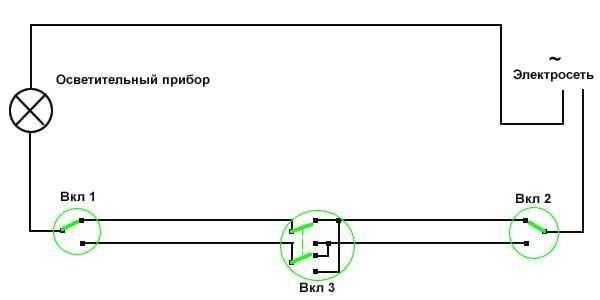
How to assemble such a circuit? Here’s the order of operations:
- Zero (and ground, if any) is wound immediately to the lamp.
- The phase is connected to the input of one of the feed-through switches (with three inputs).
- The input of the second one is fed to the free wire of the lamp.
- Two outputs of one three-terminal device are connected to the input of a crossing switch (with four inputs).
- The two outputs of the second three-pin device are fed to the second pair of contacts of the four-input switch.
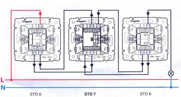
The same scheme, but from a different perspective – where to connect the wires on the housings.
And this is approximately how to divide the room.
If you need a scheme for four, five and more points, then it differs only in the number of cross switches (with four inputs/outputs). There are always two switches (with three inputs/outputs) in any circuit – at the very beginning and at the very end of the circuit. All other elements are cross-over devices.
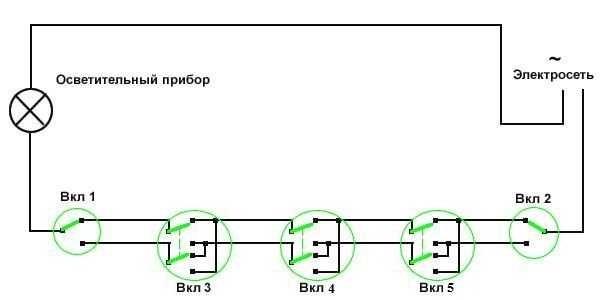
Remove one “crossover”, get a control scheme of four points. Add more – there will be a scheme for 6 control points.
To finalize everything in your head, watch this video.
On the rules of connecting wires in the junction box read here.
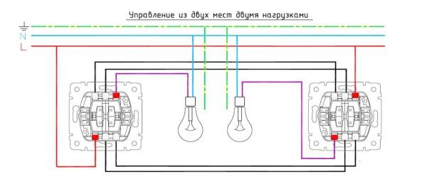
Two-key pass-through switch: wiring diagram
To control the lighting of two lamps (or groups of lamps) from several places from one switch there are two-key pass-through switches. They have six contacts. If necessary, the common wires are found according to the same principle as in a conventional device of this type, only more wires will have to be wired.
The connection scheme of the 2-key pass-through switch differs only in that there will be more wires: the phase must be fed to both inputs of the first switch, as well as from the two inputs of the second must go to two lamps (or two groups of lamps, if we are talking about a multi-arm chandelier).
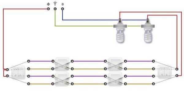
If you need to organize the control of two light sources from three or more points, you will have to put two crossing switches at each point: two-key switches simply do not have them. In this case, one pair of contacts winds up on one crossing switch, the second – on the other. And further, if necessary, they are connected to each other. On the last in the chain two-key transitional switch connect the outputs of both crossroads.
If you think about it, everything is not so complicated, and the scheme for connecting a pass switch from 2 points, so simple in general. Only there are a lot of wires…


Connecting a feed-through switch was a game changer for my apartment! When I set it up, I could finally control the lights from both ends of my long hallway. Super handy for those late-night bathroom trips! Totally worth the effort and made my place feel that much cozier!
Connecting a feed-through switch is a game changer! I did it for my hallway, and now I can control the lights from both ends. It’s super convenient, especially when my hands are full. Trust me, once you try it, you’ll wonder how you lived without it!
Hey, I tried connecting a feed-through switch last month, and it was simpler than I thought! Just follow the wiring diagram carefully, and make sure to double-check connections. It’s super handy for controlling lights from different spots in my house—totally worth the effort! Give it a go!