

With rising electricity prices, one has to think about more economical lighting fixtures. One of them use daylight illuminators. The connection scheme of fluorescent lamps is not too complicated, so that even without special knowledge of electrical engineering can be sorted out.
Περιεχόμενο άρθρου
Principle of operation of a fluorescent luminaire
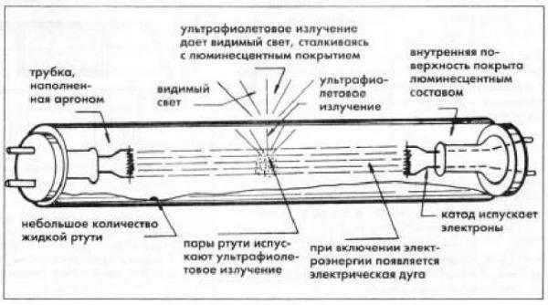
Daylight luminaires use the ability of mercury vapor to emit ultraviolet waves under the influence of electricity. In the range visible to our eyes, this radiation is translated by substances – phosphors.
Therefore, an ordinary fluorescent lamp is a glass bulb, the walls of which are covered with phosphors. Inside there is also a certain amount of mercury. There are two tungsten electrodes that provide the emission of electrons and heating (vaporization) of mercury. The flask is filled with inert gas, most often argon. Glow begins in the presence of mercury vapor heated to a certain temperature.
But for the vaporization of mercury, the usual voltage of the network is not enough. To start work in parallel with the electrodes include starter-regulating devices (abbreviated as PRA). Their task is to create a short-term voltage surge necessary for the start of glow, and then limit the operating current, preventing its uncontrolled increase. These devices – control gear – are of two types – electromagnetic and electronic. Accordingly, the schemes are different.
Schemes with a starter
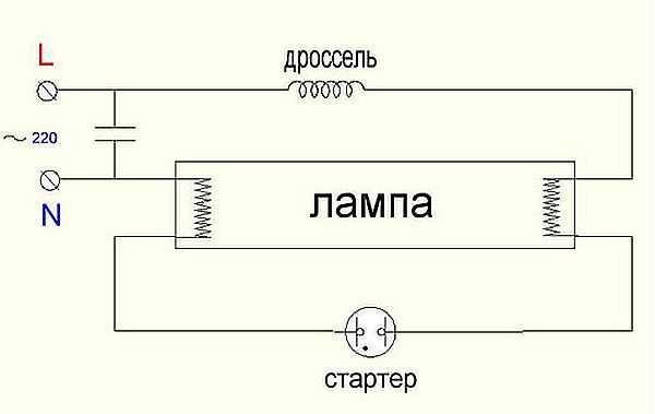
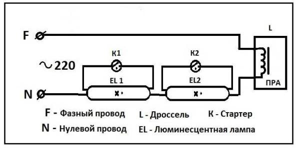
The very first schemes with starters and chokes appeared. These were (in some variants and are) two separate devices, each of which had its own socket. There are also two capacitors in the circuit: one is included in parallel to stabilize the voltage, the second is in the starter housing, it increases the duration of the starting pulse. Called all this “economy” – electromagnetic ballast. The scheme of the fluorescent lamp with a starter and a choke in the photo below.
Here’s how it works:
- When the power is turned on, current flows through the choke, hits the first tungsten spiral. Then, it goes through the starter to the second coil and out through the zero conductor. At the same time, the tungsten filaments gradually glow, as do the starter contacts.
- The starter consists of two contacts. One is stationary, the second is movable bimetallic. In the normal state they are open. When current flows, the bimetallic contact heats up, causing it to bend. Once bent, it connects to the stationary contact.
- As soon as the contacts are connected, the current in the circuit instantly increases by a factor of 2-3. It is limited only by the choke.
- Due to the sudden surge, the electrodes heat up very quickly.
- The bimetallic plate of the starter cools down and breaks the contact.
- At the moment of breaking the contact, a sudden voltage surge occurs at the throttle (self-induction). This voltage is sufficient for electrons to penetrate the argon medium. Ignition occurs and gradually the lamp enters the operating mode. It comes after all the mercury has vaporized.
The operating voltage in the lamp is lower than the mains voltage for which the starter is designed. Therefore, after ignition, it does not work. In a working lamp, its contacts are open and it does not participate in its operation.
This scheme is also called electromagnetic ballast (EMB), and the scheme of operation electromagnetic ballast – EmPRA . Often this device is simply called a choke.
The disadvantages of this scheme of connection of the fluorescent lamp are enough:
- pulsating light, which negatively affects the eyes and they quickly get tired;
- noises during start-up and operation;
- inability to start at low temperatures;
- long start-up time – from the moment of switching on it takes about 1-3 seconds.
Two tubes and two starters
In luminaires for two daylight lamps, two sets are connected in series:
- the phase wire is fed to the choke input;
- from the choke output goes to one contact of lamp 1, from the second contact goes to starter 1;
- from the starter 1 goes to the second pair of contacts of the same lamp 1, and the free contact is connected to the zero power wire (N);
In the same way the second tube is connected: first the throttle, from it – to one contact of lamp 2, the second contact of the same group goes to the second starter, the output of the starter is connected to the second pair of contacts of the lighting device 2 and the free contact is connected to the zero input wire.
The same wiring scheme for a two-lamp daylight fixture is demonstrated in the video. Perhaps, so it will be easier to deal with the wires.
Scheme for connecting two lamps from one choke (with two starters)
Practically the most expensive in this scheme are the chokes. You can save money and make a two-lamp lamp with a single choke. How – see in the video.
Electronic ballast
All the disadvantages of the scheme described above stimulated research. As a result, a scheme of electronic ballast was developed. It does not supply the network frequency of 50Hz, but high-frequency oscillations (20-60 kHz), thereby removing a very unpleasant for the eyes flashing light.
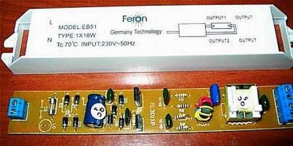
An electronic ballast looks like a small block with terminals. Inside there is one printed circuit board, on which the entire circuit is assembled. The unit has small dimensions and can be mounted in the housing of even the smallest luminaire. The parameters are selected so that the startup is fast, silent. No other devices are needed for operation. This is the so-called starterless switching scheme.
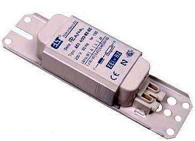
Each device has a diagram on the back side. It is immediately clear how many lamps are connected to it. The information is duplicated in the inscriptions. The power of lamps and their number are indicated, as well as the technical characteristics of the device. For example, the unit in the photo above can serve only one lamp. There is a diagram of its connection on the right. As you can see, there is nothing complicated. You take the wires, connect the conductors with the specified contacts:
- the first and second contacts of the block output connect to one pair of lamp contacts:
- the third and fourth pins are connected to the other pair;
- to the input you supply power.
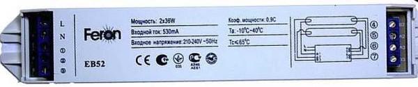
That’s it. The lamp works. The scheme of connecting two fluorescent lamps to the EB is not much more complicated (see the scheme on the photo below).
The advantages of electronic ballasts are described in the video.
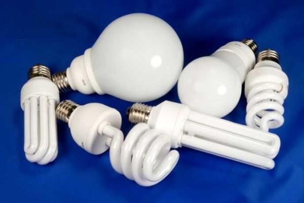
The same device is installed in the base of daylight lamps with standard sockets, which are also called “economy lamps”. This is a similar lighting device, only greatly modified.

")


I remember when I was redoing my kitchen lights, and those wiring diagrams for fluorescent lamps were a lifesaver! They made it so easy to figure out what goes where. It’s amazing how a good diagram can turn a daunting task into a fun project! Thanks for sharing!
Totally get that! I once tackled my garage setup, and a simple blueprint helped me visualize everything. It turned chaos into creativity! It’s wild how little things can make a big difference. Glad you had a smooth kitchen upgrade!
I remember when I first tackled wiring fluorescent lamps. Those diagrams were a game changer! Once I understood the layout, it was smooth sailing. Just follow the color codes, and you’ll get it right. It’s crucial for avoiding those pesky flickers and ensuring safety!