
")
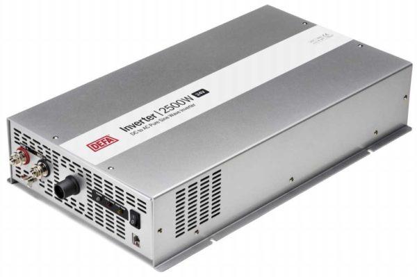
In order to connect household appliances to the onboard electrical system of the car, you need an inverter that can increase the voltage from 12V to 220V. On the shelves of stores they are available in sufficient quantity, but not happy with their price. For those who are a little familiar with electrical engineering there is an opportunity to collect a voltage converter 12 220 volts with their own hands. Two simple schemes we will parse.
Obsah článku
Converters and their types
There are three types of converters 12-220 V. The first – from 12 V get 220 V. Such inverters are popular with motorists: through them you can connect standard devices – TVs, vacuum cleaners, etc. Reverse conversion – from 220 V to 12 V – is required infrequently, usually in rooms with severe operating conditions (high humidity) to ensure electrical safety. For example, in steam rooms, swimming pools or bathrooms. In order not to risk, the standard voltage of 220 V is reduced to 12, using the appropriate equipment.
The third option is rather a stabilizer based on two converters. First, the standard 220 V is converted to 12 V, then back to 220 V. Such a double conversion allows you to have a perfect sine wave at the output. Such devices are necessary for the normal operation of most household appliances with electronic control. In any case, when installing a gas boiler is strongly advised to power it through such a converter – its electronics is very sensitive to the quality of power, and the replacement of the control board costs about as much as half of the boiler.
Pulse converter 12-220V for 300W
This circuit is simple, parts are available, most of them can be extracted from a computer power supply or bought in any radio store. The advantage of the scheme – the simplicity of implementation, the disadvantage – a non-ideal sinusoid at the output and frequency above the standard 50 Hz. That is, you can not connect to this converter devices that require power supply. To the output directly can be connected not very sensitive devices – incandescent lamps, iron, soldering iron, phone charger, etc.
The presented scheme in normal mode gives out 1.5 A or pulls a load of 300 W, at the maximum – 2.5 A, but in this mode will be noticeably warm transistors.
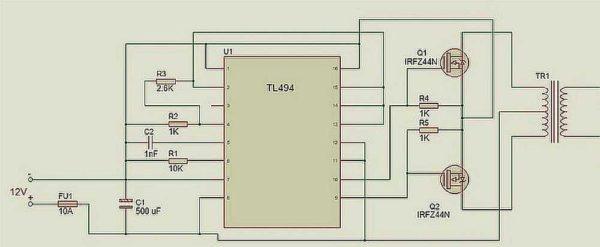
The circuit is built on the popular TLT494 PWM controller. Field-effect transistors Q1 Q2 should be placed on heatsinks, preferably separate. When installing on one heatsink, put an insulating pad under the transistors. Instead of the IRFZ244 indicated in the diagram, you can use IRFZ46 or RFZ48, which are close in characteristics.
The frequency in this 12 V to 220 V converter is set by resistor R1 and capacitor C2. The ratings may be slightly different from those shown in the schematic. If you have an old inoperable unperboynik for a computer, and in it – a working output transformer, you can put it in the scheme. If the transformer is inoperable, remove the ferrite ring from it and wind the windings with 0.6 mm copper wire. First, the primary winding is wound – 10 turns with a lead from the middle, then, on top – 80 turns of the secondary.
As already mentioned, such a voltage converter 12-220 V can only work with a load that is insensitive to power quality. To be able to connect more demanding devices, a rectifier is installed at the output, at the output of which the voltage is close to normal (scheme below).
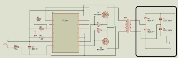
High-frequency diodes of HER307 type are specified in the scheme, but they can be replaced by FR207 or FR107 series. It is desirable to select capacitances of the specified value.
Inverter on a chip
This voltage converter 12 220 V is assembled on the basis of a specialized chip KR1211EU1. It is a generator of pulses that are taken from outputs 6 and 4. Pulses are antiphase, between them a small time interval – to avoid simultaneous opening of both keys. The chip is powered by a voltage of 9.5 V, which is set by a parametric stabilizer on the stabilizer D814V.
Also in the circuit there are two field-effect transistors of increased power – IRL2505 (VT1 and VT2). They have a very low resistance of the open output channel – about 0.008 ohms, which is comparable to the resistance of a mechanical key. The permissible direct current is up to 104 A, pulse current – up to 360 A. Such characteristics actually allow to obtain 220 V at a load of up to 400 W. Install transistors must be installed on heat sinks (at a power of up to 200 W you can do without them).
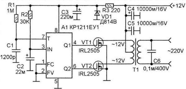
The frequency of pulses depends on the parameters of resistor R1 and capacitor C1, at the output there is a capacitor C6 to suppress high-frequency emissions.
It is better to take a ready-made transformer. In the circuit it is included in reverse – the low-voltage secondary winding serves as the primary winding, and the voltage is taken from the high-voltage secondary winding.
Possible substitutions in the element base:
- Stabilizer D814V specified in the circuit can be replaced by any one that produces 8-10 V. For example, KC 182, KC 191, KC 210.
- If there are no capacitors C4 and C5 of the K50-35 type for 1000 µF, you can take four 5000 µF or 4700 µF and turn them on in parallel,
- Instead of imported capacitor C3 220m you can put domestic capacitor of any type for 100-500 µF and voltage not lower than 10 V.
- Transformer – any transformer with capacity from 10 W to 1000 W, but its capacity should be at least twice as high as the planned load.
When installing the transformer, transistor and 12 V connection circuits, it is necessary to use large cross-section wires – the current here can reach high values (at 400 W power up to 40 A).
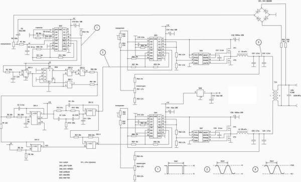
Inverter with pure sine wave output
Schemes of bottom converters are complicated even for experienced radio amateurs, so it is not easy to make them with your own hands. An example of the simplest scheme below.
In this case, it is easier to assemble such a converter from ready-made boards. How – see in the video.

The following video tells how to assemble an inverter for 220 volts with pure sine. Only the input voltage is not 12 V, but 24 V.
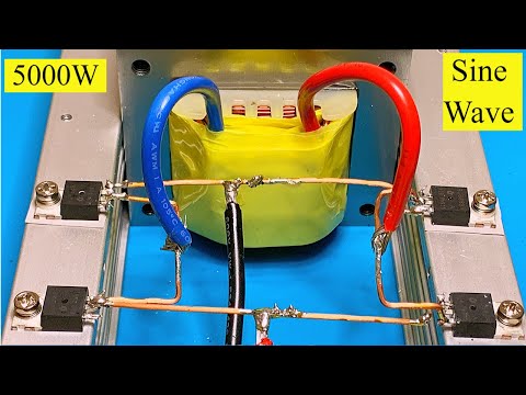
And this video shows how you can change the input voltage, but get the required 220 V at the output.


")


