

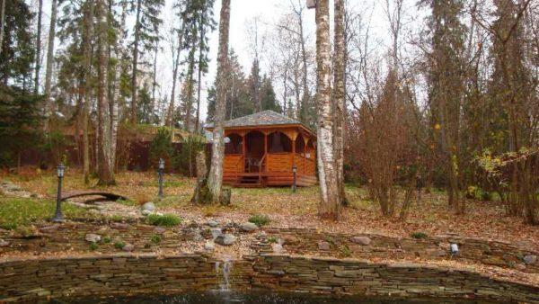
In some regions, groundwater is very close to the surface. So close that they threaten the integrity of buildings (their foundations) and prevent plantings from growing. All these problems are solved by site drainage. In general, this event is costly and on the amount of required funds and the necessary time. Much of the time is spent on planning. If you do everything wisely, you need data from hydrogeological research and the project, drawn up by a specialist. But, as usual, so do few, most do the drainage system with their own hands.
Isi artikel
What water is drained by drainage
Site drainage is a costly and labor-intensive event that requires a large amount of land work. The best time for construction is the process of planning and arrangement of the site. Later terms of fulfillment lead to a big mess, which is not everyone happy. Nevertheless, if there is standing water on the plot, you have to go for it as well.
There are several types of water on the site that bother us and need to be diverted. They have a different character and require different measures.
Surface water
They are formed during snowmelt and heavy precipitation, when working on the plot (watering, washing paths), releasing water from a reservoir, etc. What all phenomena have in common is their one-time nature: surface water appears after certain events. A more sensible way to divert them is to install a storm water drainage system. It copes with the task on “excellent”, and the cost of arrangement is much lower.
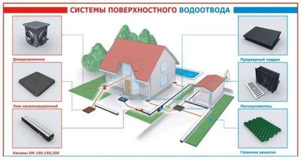
For the removal of surface water put mainly open channels, the reception of water – point under the storm pipes or linear along the entire overhang of the roof. From these receivers, water is taken away by solid plastic (asbestos-cement) pipes into a drainage ditch or discharged into a ravine, river or lake. Sometimes the output to the ground is allowed.
Groundwater
Those ground waters, which have seasonal level (higher in spring after the flood, lower in winter), have a zone of supply (where they come from) and outflow (where they go) are called ground waters. Usually groundwater is present in sandy, sandy loamy soils, less often – in loams with a small amount of clay.
The presence of groundwater can be determined using self-drilled pits or several hand-drilled boreholes. When drilling, the dynamic level (when water appeared during drilling) and established (after some time after its appearance, its level stabilizes) are noted.
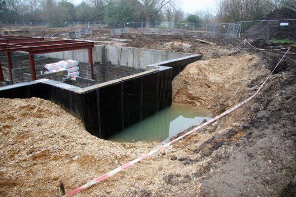
If we talk about the removal of water from the building, the drainage system is arranged if the groundwater level (UGV) below the foundation is only 0.5 m. If the groundwater level is high – above the frost depth – then a monolithic slab foundation with water drainage measures is recommended. If the water table is lower, other options are possible, but a thorough and multi-layered waterproofing is required. The need for foundation drainage should be evaluated by specialists.
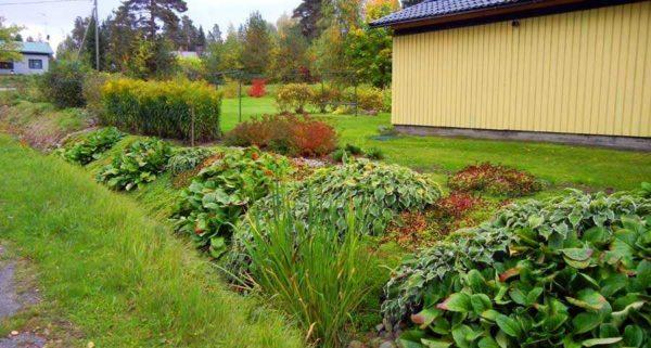
If high standing groundwater (groundwater table above 2.5 meters) prevents plants from growing, drainage of the site is required. This is a system of channels or special drainage pipes laid in the ground at a certain level (20-30 cm below the groundwater table). The depth of pipes or ditches – below the groundwater table – so that water flows to lower places. In this way the adjacent soil areas are drained.
Topsoil water
This groundwater occurs in soils with high water bearing strata, but is often the result of construction errors. Usually it is water that soaks into the soil and encounters strata with low water absorption capacity. Most often it is clay.
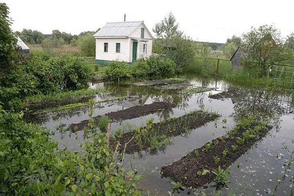
If after the rain on the site stand and puddles do not go away for a long time – it’s water table. If water accumulates in the ditches dug – this is also high water. If a few years after the construction of the house on clay soils or loams in the basement walls begin to “cry” – this is also a high water table. Water accumulated in gravel pockets under the foundation, in the pavement, etc.
Drainage of top water is easiest to do with the help of ditches, but it is better to prevent its appearance – to backfill the foundation not with rubble and sand, but with clay or native soil, carefully tamping it layer by layer. The main task is to exclude the presence of pockets in which water will accumulate. After such a backfill is required to make a pavement, which is wider than the backfill and an obligatory touch – drainage of storm water.
If the site has a slope, think about the arrangement of terraces and retaining walls, with the obligatory arrangement of drainage ditches along the retaining wall. It is most difficult to fight with water table on low plots, which are at a level lower than the neighboring ones. Here a reasonable solution is to backfill the ground, since usually there is nowhere to dump water. Another possible option is to lead the drain through neighboring plots or along the road to the point of possible discharge. It is necessary to decide on the spot, based on the available conditions.
Not to do drainage
The device of the drainage system is an expensive measure. If it is possible to do without other measures, it is worth doing so. Other measures include the following activities:
- Arranging a storm drainage system.
- Arrangement of a pavement (it is desirable to insulate the pavement for pudgy soils).
- On sites with a slope device upland ditch – a ditch of sufficient depth, which is located on a slope higher than the house. From this ditch water is diverted below the site, in a drainage ditch, discharged into a ravine, river, lake, etc.

- Foundation waterproofing. To eliminate capillary moisture suction on top of the finished foundation lay several layers of waterproofing material, to eliminate problems with damp walls in the basement make external waterproofing of the foundation (dug to the full depth and treated with waterproofing materials). For greater reliability from the inside of the walls of the basement and / or basement floor to treat penetrating waterproofing such as “Penetron”.
If after all these measures you are not satisfied with the situation, it makes sense to make a drainage system.
Types of drainage
Site drainage is a complex system with many nuances and peculiarities. By structure, it can be local (local) – to solve the problem on a particular site. Most often it is the drainage of the foundation, basement and semi-basement (basement) floors. Also, water drainage systems on the site can be general – to drain the entire site or a significant part of it.
By method of installation
According to the method of installation, the drainage system can be:
- Open. Concrete or stone trays are used, ditches are dug along the plot. They remain open, but can be covered with decorative grates to protect the system from large debris. If you need a simple solution for the drainage of surface water in the dacha – it is exactly the ditches around the perimeter of the site or in the lowest zone. Their depth should be sufficient to ensure that at maximum flow the water does not overflow. To unreinforced walls of drainage ditches do not collapse, they are made at an angle of 30 °,
The specific type of site drainage is selected based on site conditions. On clays and loams need extensive gravel and sand zone, which will flow water from the surrounding areas of the soil. On sands and sandy loams there is no need for such a cushion – the soils themselves drain water quite well, but only a specialist can say specifically on the results of geological studies.
By type of realization
There are several types (schemes) of drainage on the site:
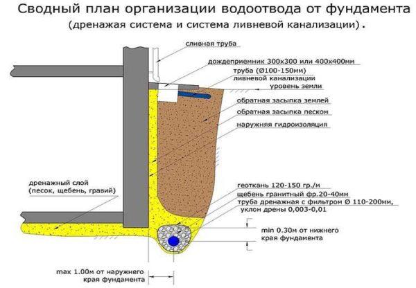
- Circular. Pipes are closed in a ring around the object. Usually it is a house. It is rarely used, as it is necessary to bury the drainage pipes – the pipe itself should be laid 20-30 cm below the groundwater table. It is expensive and difficult to perform.
- Wall drainage – to divert water away from the walls. It is located at a distance of 1.6-2.4 m from the walls (in no case close). In this case, the drain is located 5-10 cm below the floor of the basement floor. If the floor is poured over a large crushed stone pad, the drain is placed 5-10 cm below this level.

- Slab drainage. It is used for slab foundations in difficult situations. Necessary for drainage of headwater, it is usually used in conjunction with wall drainage. Plast drainage is a layer poured into the pit – sand, crushed stone, waterproofing (as they are poured from bottom to top). On top of this cushion, reinforcement is already laid and the foundation slab is poured.
- Systematic and radial. They are used for draining sites. They differ in the way the drains are located relative to the central pipe. At the beam scheme the system looks like a herringbone (already existing plants can be taken into account), at the systematic scheme the drains are laid with a calculated step (arranged usually when planning the site).

When draining the site, the central drain or collector is made of pipes with a larger diameter (130-150 mm vs. 90-100 mm for conventional drains) – the volume of water here is usually greater. The specific type of drainage system is selected based on the tasks that need to be solved. Sometimes it is necessary to apply a combination of different schemes.
Site drainage – device
The drainage system consists of a network of interconnected pipes, which are located along the perimeter (or on the area) of the territory protected from water. In places of intersection or turns put drainage wells. They are necessary for controlling the condition of the system and cleaning silted pipes. From all drained areas, water flows into the collector well, where it accumulates to a certain level. Then it can be discharged or used for irrigation and other technical needs. Discharge can go by gravity (if there is a place), and to supply for irrigation and other technical needs are used submersible drainage pumps.
Drainage pipes and wells
Pipes for drainage are used special – with holes ranging in size from 1.5 to 5 mm. Water from the surrounding soil enters through them. The holes are located on the entire surface of the pipe. They come in different diameters, for private homes and plots the most used size of 100 mm, for drainage of large volumes of water can be taken cross-section up to 150 mm.
They are now made mainly of polymers – HDPE, LDPE (low and high pressure polyethylene) and PVC (polyvinyl chloride). They are used for laying to a depth of up to 2 meters. There are also two and three-layer combined, which are made of combinations of these materials, they are buried to a depth of up to 5 meters.
Pipes for drains are selected taking into account the depth of burial. It is necessary to select by ring stiffness. It is denoted by the Latin letters SN and the following numbers, showing the ring stiffness (resistance to loads). For laying to a depth of up to 4 meters the stiffness should be SN4, up to 6 meters – SN6.
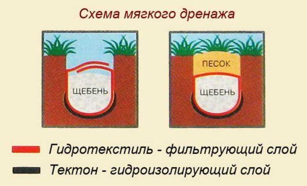
The surface of the drainage pipe is wrapped with filtering materials. Filtering layers can be from one to three. The number of layers is selected based on the composition of the soil – the finer the particles, the more layers are required. For example, pipes with three filtering layers are used on clays and loams.
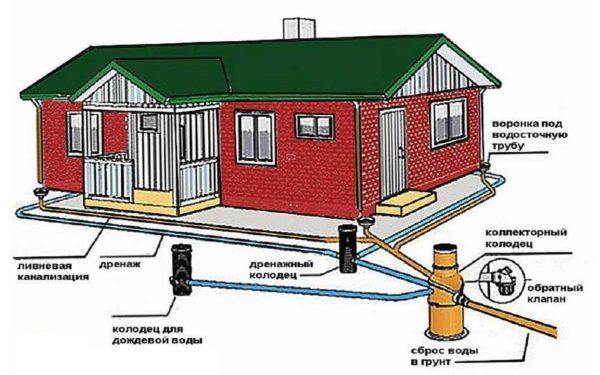
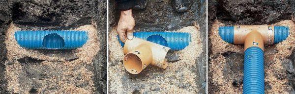
At the turning points and in places where several pipes are connected, revision wells are placed. They are necessary for easier cleaning in case of clogging, as well as for the possibility of monitoring the condition of the pipes. As a rule, all pipes converge into one collector well, from where water is either sent by gravity to the point of discharge, or pumped out forcibly.
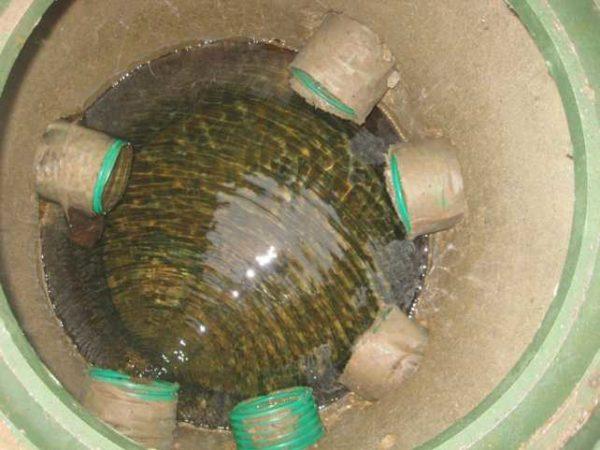
There are wells special – for drainage systems, but it is quite possible to bury a concrete ring with a bottom and a cover of small diameter (70-80 cm) and lead the pipes into it. Depending on the depth of laying the drain, several rings may be required. Another option is to make an inspection well and a drainage pipe of large size, but in this case you will have to think of something with the bottom. For example, you can pour the bottom with concrete.
Slope
In order for the collected water to flow away on its own, it is necessary to maintain a certain slope towards the direction of travel. The minimum slope is 0.002 – 2 mm per meter, the basic slope is 0.005 (5 mm per 1 meter of pipe). If the drainage is shallow, the slope of the pipe can increase to 1-3 cm per 1 meter, but make it should be the minimum possible. When the flow velocity is more than 1 m/sec there is a “sucking” of small soil particles, which contributes to faster silting of the system.
The slope is changed (in relation to the “duty” in 5 mm per 1 meter) in two cases:
- If it is necessary to withdraw more water per unit of time without increasing the diameter of the drain. In this case the slope is increased.
- If it is necessary to avoid the backwater (when the pipe laid with a given slope will be below the groundwater table, i.e. water simply will not flow down). In this case, the slope is reduced.
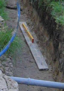
In the practical construction of the system, questions may arise as to how to ensure the specified slope. You can do this with a laser level (leveler), using a water level (not very convenient) or a level board paired with an ordinary construction bubble level. Having leveled the bottom of the trench, lay a board, on it – the level. Moving it on the board, check and correct the slope of the trench bottom in some area.
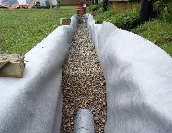
Technology of installation of the drain
Trenches of a given width and depth are dug in advance. The bottom of the trench is leveled and tamped. Do not forget about the slope, but at this stage there is no point in keeping it exactly. Next pour about 100 mm of coarse-grained washed river sand, it is also tamped (poured, then pass tamping), leveled. Sand is desirable fraction Dsr 1.5-2.5 mm.
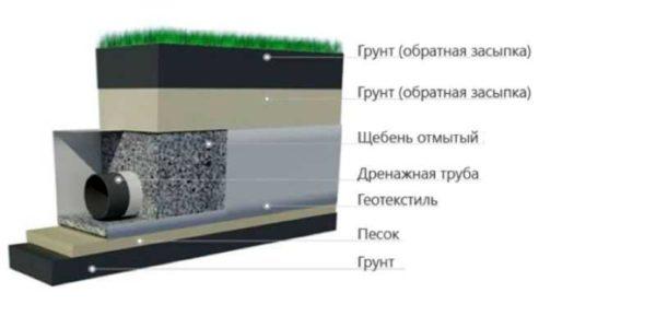
On the sand is laid geotextile with a density of no more than 200 g/m2. The edges of the cloth are laid along the walls of the trench. A layer of granite crushed stone is poured on top. The size of crushed stone fraction is chosen depending on the size of holes in the drainage pipe. For the smallest holes require crushed stone with a grain of 6-8 mm, for the rest – larger. The thickness of the crushed stone layer – 150-250 mm – depending on the type of soil. On clays and loams 250 mm is required, on soils that drain water better – sands and sandy loam – about 150 mm.
Crushed stone is tamped, leveling it into a given slope. A drainage pipe is laid on the compacted crushed stone. Then the pipe is layer by layer covered with gravel, each layer is tamped. There should be at least 100 mm of gravel on top of the drain. After that, the ends of geotextile are wrapped, their overlap should be 15-20 cm. A layer of sand with 0.5-1 mm particles is poured on top. The thickness of the sand layer is 100-300 mm, also depending on the water permeability of soils: the worse the water drainage, the thicker the sand layer. The “native” soil is laid on the tamped sand, and then plants can be planted.
A little about the materials for backfilling
Crushed stone should be granite or other hard, lime-free rocks. Dolomite (lime) or marble are not suitable. To test the existing one is simple: drop vinegar on it. If there is a reaction, it is not suitable.
Once again, pay attention: the crushed stone is laid washed – so that the new pipes did not immediately silt up.
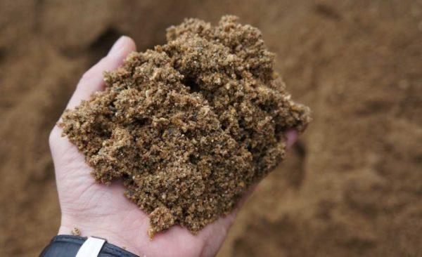
Coarse-grained sand is required. The grain size is from 0.5 mm to 1 mm. The sand should also be clean. Some of the sand is poured with clean water, stirred up, wait until the sand settles and assess the purity of the water. If the water is cloudy, with a lot of suspended particles, the sand requires washing.
Some nuances of construction
When draining the site, the central drain or collector is made of pipes with a larger diameter (130-150 mm versus 90-100 mm for conventional drains) – the volume of water here is usually greater.
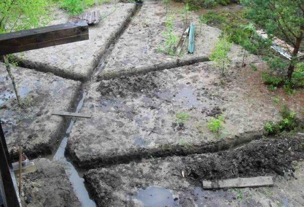
Drainage device on the site start from the lowest point and move gradually upwards. First, a collector well is installed. When the groundwater level is high or when the top water has not yet descended, water can accumulate in the ditches. This muddy sludge will roll into the well, clogging it. In addition, the presence of water in the ditch greatly interferes with the work: drains should be laid in dry ditches. To drain them along the course of the ditch make side pits (sumpf) of greater depth. Crushed stone is poured at the bottom. The accumulated water is pumped out of these pits.


